Integrated lithium battery energy storage solutions

Communication Integration|Site deployment

Integrate multi-vendor devices, protocols and networks into a diagnosable communication system

Communication integration and deployment for large BESS sites — topology, VLAN, redundancy, diagnostics and cable engineering.

  • Multi-vendor devices
  • Multiple protocols
  • Layered networks
  • Security zones
  • Redundant & reliable
  • Diagnosable O&M
Network KPI TC-NET-26-015 Demo data · NET-B3.0
Devices
54 nodes
Switches
12 units
VLANs
Z1–Z5 + OOB
Env
MRP demo
Protocols
6 families
PTP
GM locked
Availability
99.98% demo
Baseline
NET-B3.0

Four communication integration values

What site network engineering must deliver beyond a protocol catalog Demo data

  • Fast multi-vendor onboarding Adapters to a shared object model
  • Layered topology & redundancy No single point of failure
  • Unified naming & semantics Tags, units, quality and time
  • Diagnosable · secure · operable Fault to device · link · zone

Device inventory RACI + physical site network topology

Who owns each class — and how five layers connect on site Demo data

Device inventory & responsibility

ClassQtyProtocolPortsOwnerCriticality
BMS / BMU32CAN / TCP2×CAN · 2×FEBattery OEMCritical
PCS16Modbus TCPETH1/2PCS vendorCritical
EMS / SCADA2IEC 61850 demoFE · FOSystemCritical
Meter / gate8Modbus TCPFEEPCHigh
HVAC / fire6Modbus RTURS485MEPHigh
O&M jump2HTTPSDMZOwner ITMedium

Physical site topology — five layers

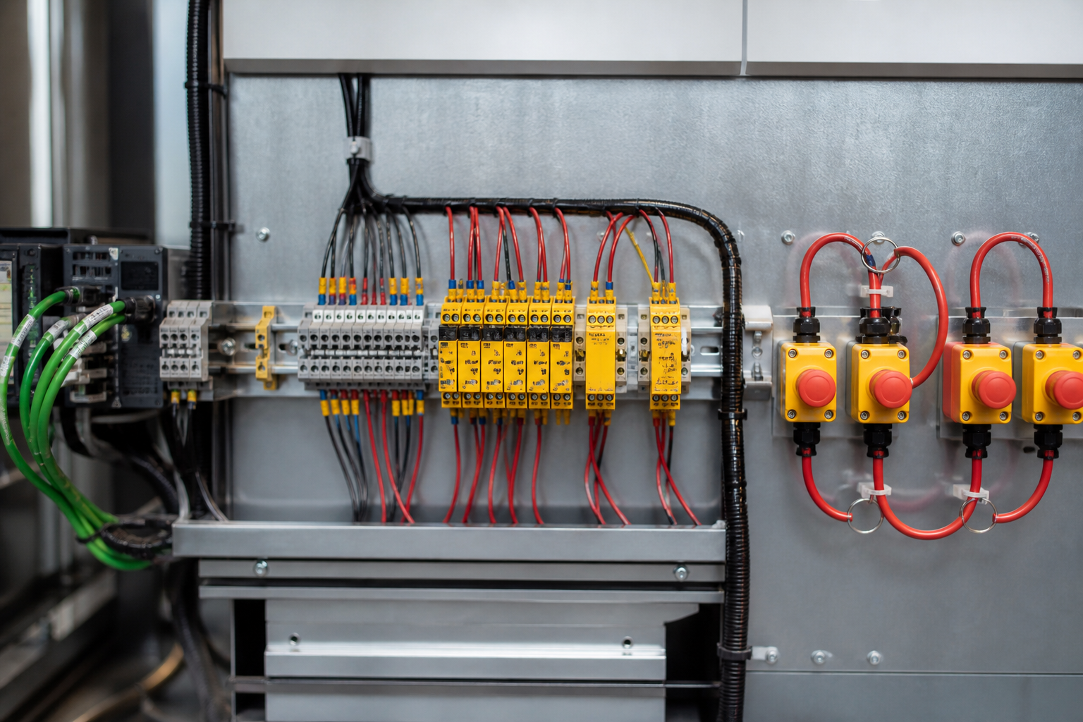
Physical site network topology backdrop (demo reuse)
  1. Device layer BMS · PCS · sensors
  2. Device control Field / control switches
  3. Station core Core L2/L3 · PTP GM
  4. DMZ / O&M Historian · jump host
  5. Controlled remote VPN · owner SCADA
  • Field bus
  • Copper
  • Fiber ring
  • Firewall
  • VPN

Semantic mapping

From heterogeneous protocols to a canonical object model

Adapters normalize units, precision, quality timestamps, buffer rates and fault mapping — ambiguous maps are rejected Demo data
  • Units
  • Precision
  • Quality + timestamp
  • Buffer / rate
  • Anomaly mapping
  1. Multi-protocol in CAN · Modbus · 61850
  2. Gateway adapter Vendor packs
  3. Canonical model Object table
  4. EMS / SCADA Northbound
  5. Reject ambiguous Red-X list
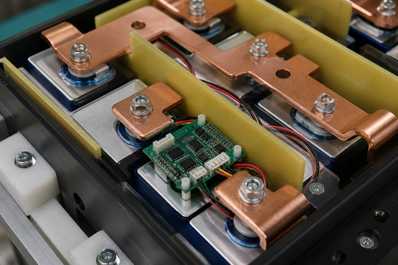
Industrial gateway for protocol mapping (demo reuse)

Rejected ambiguous maps (demo)

  • Voltage without unit / scale
  • Setpoint without quality bit
  • SOE without PTP time
  • Duplicate Modbus IDs

IP / VLAN address plan + naming & identity rules

Z1–Z5 plus OOB template — no flat LAN, no duplicate IDs Demo data · site TCN26

Address plan template

ZoneVLANSubnetGatewayRole
Z1 Device1010.10.10.0/2410.10.10.1Field devices
Z2 Control2010.10.20.0/2410.10.20.1Control switches
Z3 Station3010.10.30.0/2410.10.30.1Core / PTP
Z4 DMZ4010.10.40.0/2410.10.40.1O&M / hist
Z5 Remote5010.10.50.0/2410.10.50.1VPN edge
OOB9910.10.99.0/2410.10.99.1Mgmt only

Naming & identity rules

Site code
TCN26
Device
PCS01 · BESS03
Port
PCS01·ETH1
VLAN tag
Z2_CTRL
Modbus unit
Locked map NET-B3.0
Tag prefix
BESS{n}/PCS{n}/EMS

Topology & redundancy design — no single point of failure

Five equal columns — dual uplink through availability under fault Demo data

Dual uplink

  • LACP / track
  • A active · B standby
  • Auto fail-over

Ring redundancy

  • MRP / RSTP / PRP
  • Control ring
  • < 50 ms demo

A/B power & link

  • Dual PSU
  • Segregated paths
  • Diverse fiber

Protection

  • Storm control
  • IGMP snoop
  • ACL deny-default

Availability under fault

  • Switchover timed
  • Alarm to EMS
  • Evidence logged

Fault localization

Network faults must resolve to device · link · zone · impact

Closed-loop diagnose — topology markers 1/2/3 with scenario table Demo data
  1. Detect Alarm / loss of link
  2. Isolate Device vs path
  3. Zone Z1–Z5 map
  4. Impact Control / O&M
  5. Evidence Mirror · log
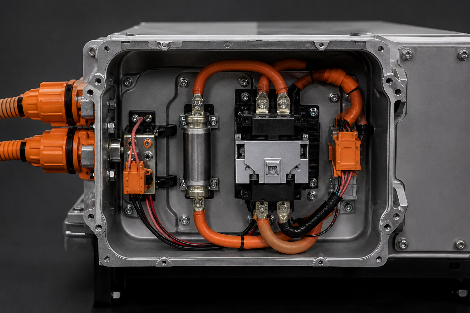
Fault localization topology scene (demo reuse)
  • Core switch Z3
  • Fiber cut Ring west
  • Uplink B Standby up

Fault scenarios

EventDetectImpactSwitchEvidence
Switch fail≤ 2 sRing segmentTo B (2 s)Syslog
Fiber cutMRPOne pathRing healOTDR / log
Port flapLink flapSingle deviceHold / blockPort mirror

Time sync & event timing · zone security architecture

GPS → PTP GM → boundary clocks plus Z1–Z5 trust and six security capabilities Demo data

Time sync chain

  1. GPS / GNSS Site antenna
  2. PTP GM Station core
  3. Boundary clock Control ring

Accuracy classes

ClassTargetUse
A≤ 1 msSOE critical
B~ 2 msControl events
C≤ 5 msO&M / hist

Zone trust levels

  • Z1 Device — least privilege
  • Z2 Control — ring only
  • Z3 Station — core trust
  • Z4 DMZ — mediated
  • Z5 Remote — MFA VPN

Six security capabilities

  • Firewall / ACL
  • RBAC
  • Jump host
  • Session log
  • USB lock
  • Patch window

Gateway capability · diagnostics · network deliverables

Three equal columns — integrate, observe, and package the network Demo data

Multi-vendor gateway integration

  • Protocol packs per vendor
  • Object model mapping UI
  • Rate / buffer policy
  • Reject ambiguous maps
  • Firmware / ICD freeze

Diagnostics & observability (E2E)

  • Link / ring health
  • PTP lock state
  • Port mirror / capture
  • SOE latency path
  • Field test toolkit

Network deliverables (~12 types)

  • Topology drawing
  • IP / VLAN plan
  • Fiber schedule
  • ACL matrix
  • PTP diagram
  • Naming register
  • Gateway map
  • FAT record
  • SAT record
  • As-built NET
  • O&M access guide
  • Change log

Cable engineering · change governance · integration stages

Physical specs, six-step interface change, and inside-out commissioning Demo data

Cable & physical engineering

  • Copper Cat6A / STP
  • Fiber OS2 · LC
  • Segregation HV/LV/IT
  • Label / patch panel
  • Ground / bonding

Change & interface governance — six steps

  1. Raise CR logged
  2. Impact Zone · ICD
  3. Approve RACI gate
  4. Implement Config push
  5. Retest Core cases
  6. Freeze Rev bump

Integration & debug stages (inside → out)

Inner

  1. Unit loopback
  2. Cabinet LAN
  3. Ring heal
  4. PTP lock

Outer

  1. Zone ACL
  2. DMZ jump
  3. Remote VPN
  4. Long soak

Network acceptance evidence + deliverables checklist

Close the integration pack — metrics with proof, then the file set Demo data · NET-B3.0

Acceptance evidence

MetricStandardResultEvidence
Ring recovery< 50 msPASSMRP log
PTP lockGM lockedPASSGM status
ACL deny-defaultICD §8PASSFW export
FAT / SATCase set94%Report pack
As-builtRev matchPASSNET-B3.0

Deliverables grid

  • Topology As-built
  • IP / VLAN Plan
  • Fiber table Schedule
  • ACL matrix FW
  • PTP diagram Time
  • FAT / SAT Evidence
  • Gateway map Objects
  • Naming register Tags
  • O&M guide Access
  • Change log Rev