










Cabinet Structure|Structural engineering
From load paths to maintenance space — define structural boundaries for large BESS cabinets
Structural engineering for safety · reliability · serviceability · scalability
-

Structural load paths
Clear load paths and redundancy for static, transport, lift and seismic cases
-

Functional zoning
Structure–function zoning to avoid interference and thermal / electrical / fire crosstalk
-

Transport & lifting robust
Lift points, CG and feet constrained together across assembly, transport and stacking
-

Serviceable & environment-ready
Ergonomic space, sealing, drainage and heat paths, coatings and replaceable parts
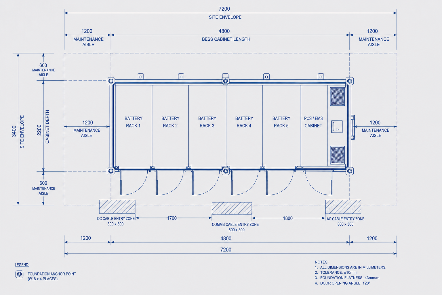
Site and equipment boundary inputs
Footprint, equipment, cooling, cabling, doors, foundation, lift path and environment freeze the structural frame before sheet-metal detail.
-
Battery & rack
Mass, layout, heat reject
-

PCS / power
Size, mass, thermal
-

Cooling & fire
Flow, pressure, relief
-
Cabling
Bend radius, trays, glands
-
Doors & service
Swing, clearance
-

Foundation
Anchor pattern, flatness
-
Transport & lift
Crane, path, CG
-

Environment
Temp, humidity, wind, corrosion
-

Expansion
Side-by-side growth
| Criterion | Template value |
|---|---|
| Structural safety factor | ≥ 1.5 static · ≥ 2.0 lift/transport |
| Material (demo) | Q355B primary · Q235B secondary |
| Plate thickness | 1.5 – 6.0 mm |
| Bolt grade | 8.8 / 10.9 |
| Welding | Continuous fillet (CFW) demo |
| Operating temperature | −30 °C to 50 °C |
| Protection / corrosion | IP55 target · C4 (C5 optional) |
| Zone | Requirement | Structure response |
|---|---|---|
| Battery compartment | Pack slide-out demo | Reinforced rails + stop |
| Cable gallery | ≥ 200 mm bend radius | Dedicated trunking zone |
| HVAC / liquid | Maintainable coil access | Removable panel + drain |
| Foundation interface | 4-point anchor M16 demo | Spread load pads FEA verified |
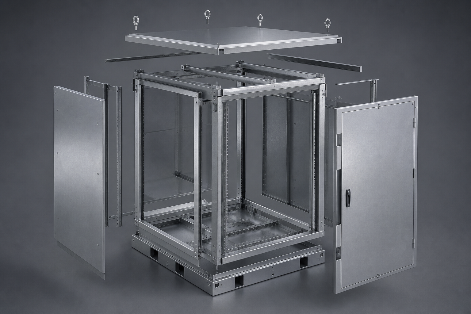
Whole-cabinet exploded structure
Signature view: load-bearing frame first · panels, doors and interfaces follow the primary path.
-
Base frame
Welded steel · anti-corrosion primer demo
-
Vertical posts
RHS primary · equipment hang points
-
Cross members
Pack support pitch demo 520 mm
-
Enclosure panels
1.5–2.5 mm · stiffener pattern REV-B
- Primary load path documented for lift + seismic cases
- Panel fastener map tied to torque spec TC-DEMO-TQ-061
- No equipment weight hung from cosmetic panels
| # | Component | Material / spec | Thickness | Join | Note |
|---|---|---|---|---|---|
| 1 | Lifting points | Q355B | — | Weld | 4× · ≥ 2.5 t demo |
| 2 | Top cover | Q235B | 2.0 mm | Bolt | Removable |
| 3 | Top frame | Q355B | RHS | Weld | Load-bearing |
| 4 | Vertical columns | Q355B | RHS 80×80×4 | Weld | Main path |
| 5 | Horizontal beams | Q355B | C-channel | Weld | Pack pitch |
| 6 | Device rack rails | Q235B | 2.5 mm | Bolt | Slide-out |
| 7 | Side panels | SPCC | 1.5 mm | Bolt | Stiffened |
| 8 | Back panel | SPCC | 1.5 mm | Bolt | Cable zone |
| 9 | Front door | SPCC | 2.0 mm | Hinge | IP55 target |
| 10 | Multi-point locks | SS | — | Assemble | 3-point |
| 11 | Sealing strips | EPDM | — | Bond | Triple seal demo |
| 12 | Cable entry plates | SPCC | 2.0 mm | Bolt | Gland plate |
| 13 | Ventilation louvers | Alu | — | Bolt | Rain hood |
| 14 | Base / chassis | Q355B | 6–10 mm | Weld | Anchor interface |
| 15 | Base skirts | Q235B | 2.0 mm | Bolt | Optional |
| 16 | Anchor bolts | 8.8 | M16–M30 | Site | Pattern REV-C |
| 17 | Grounding lugs | Cu | — | Bolt | Equipotential |
The cabinet is not a shell
It is the shared structure for equipment loads, environmental boundaries and maintenance actions.
-
Battery
Energy density · structural load priority
-
High voltage
PCS / bus · electrical isolation
-
Control
LV wiring · EMC shielding
-
Thermal
Fans / exchangers · port alignment
-
Fire & relief
Detection · pressure relief
-
Service
Front / rear / side human access
- Safety and seismic resistance
- Electrical isolation and protection
- Non-interfering thermal paths
- Pressure relief without structural conflict
- Maintenance actions without interference
- Long-term sealing and corrosion readiness
- Transport and lifting reliability
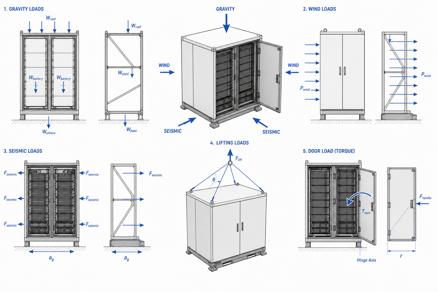
Engineered load-path decomposition
Rated mounts and free-body cases for packs, doors, cables, cooling, wind, snow, transport, lift and seismic inertia.
- Pack stack load
- 4.2 t / bay demo
- PCS mount
- 800 kg · 4-point
- Safety factor
- ≥ 2.0 static
- Deflection limit
- ≤ 2 mm @ rated
-
Equipment static
Gravity of internal mass
-
Door torque
Open-door frame moments
-
Cable / bus tension
Internal routing loads
-
Cooling equipment
HVAC / fan mass
-
Maintenance pull-out
Slide-tray forces
-
Wind load
Static pressure on enclosure
-
Snow load
Roof downward pressure
-
Transport shock
Road handling accelerations
-
Lifting case
Eyes + frame integrity
-

Seismic inertia
Dynamic 0.4g demo
Structure reliability + manufacturing feasibility
Scheme choice, material thickness and critical joints must be both strong and buildable.
-
Materials
Q235B / Q355B · 1.5–6.0 mm demo
-
Profiles
RHS · C-channel · angle
-
Fasteners
8.8 / 10.9 · torque map
-
Critical joints
Base · column · lift pad FEA
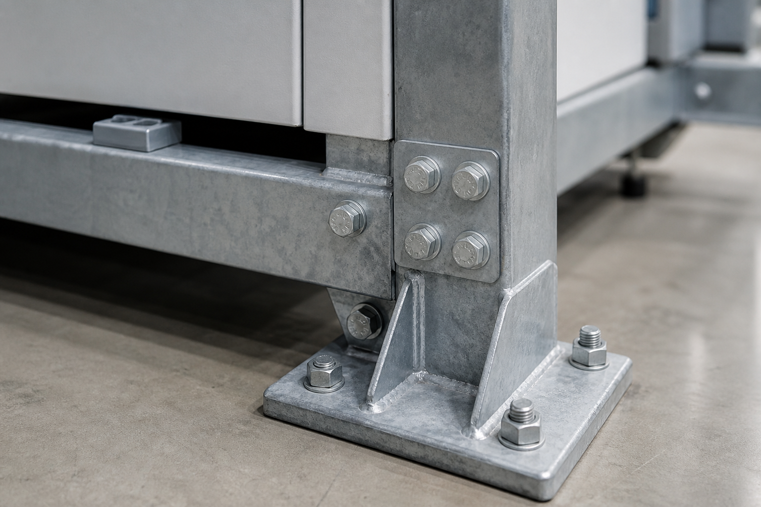
| Item | Scheme A · full weld | Scheme B · modular / bolted |
|---|---|---|
| Stiffness | Higher | Good · joint design critical |
| Process time | Longer | Shorter · ship-friendly |
| Best fit | Low volume · complex | Series production |
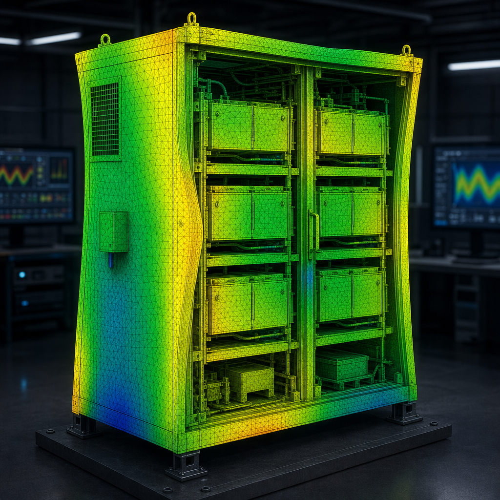
FEA evidence · static / transport / lift / seismic
Structural conclusions supported by simulation cases and a clear pass table · demo values only.
-
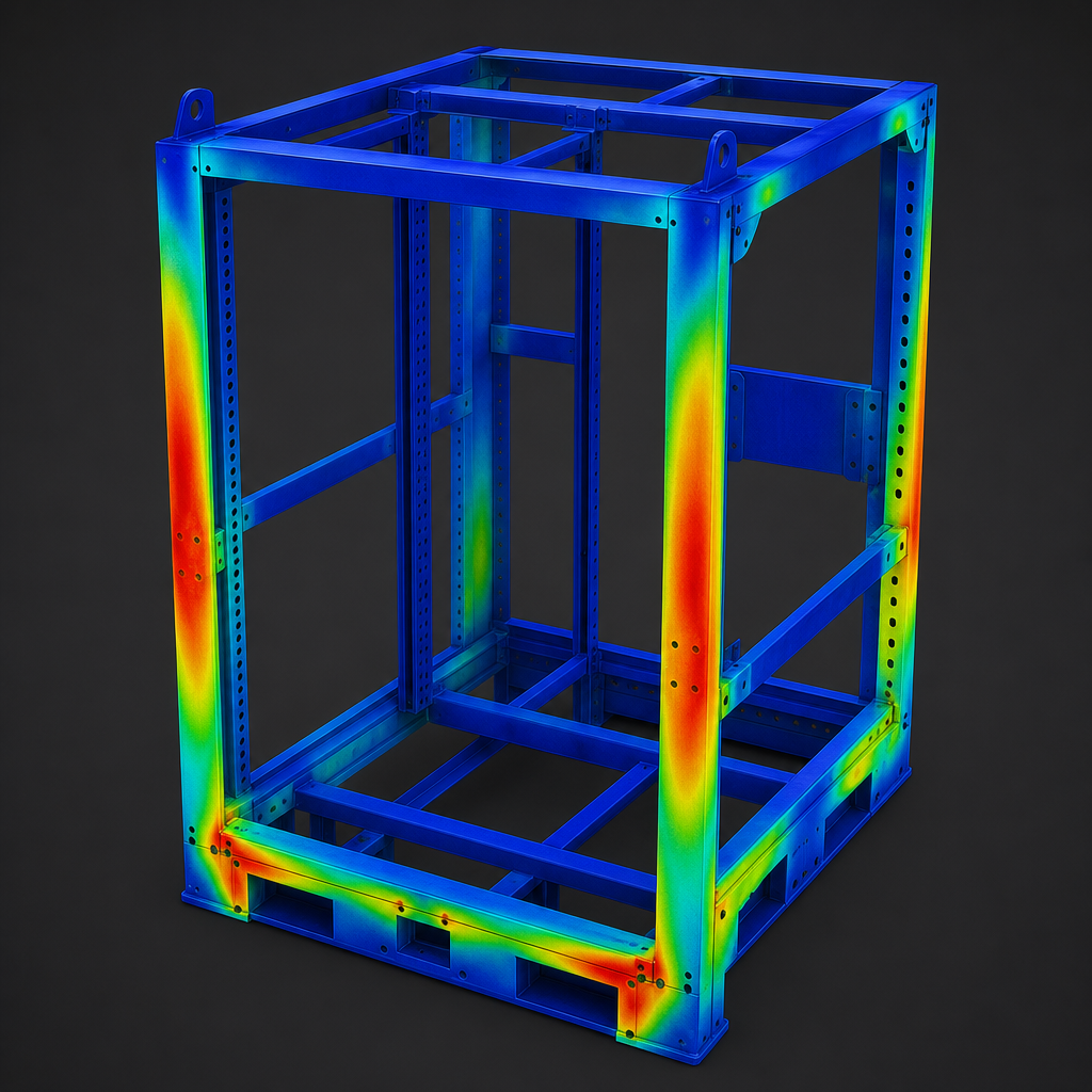
Von Mises stress
-
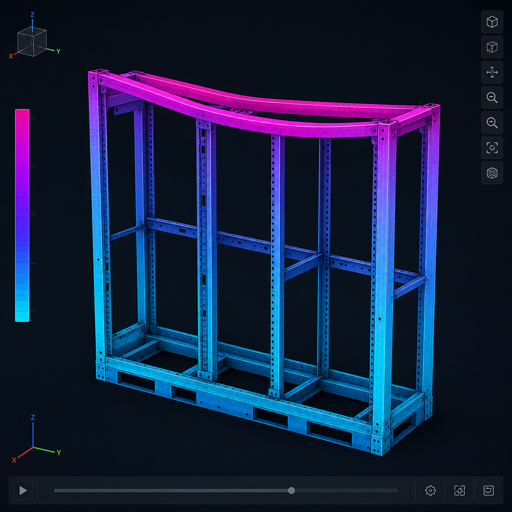
Displacement
-
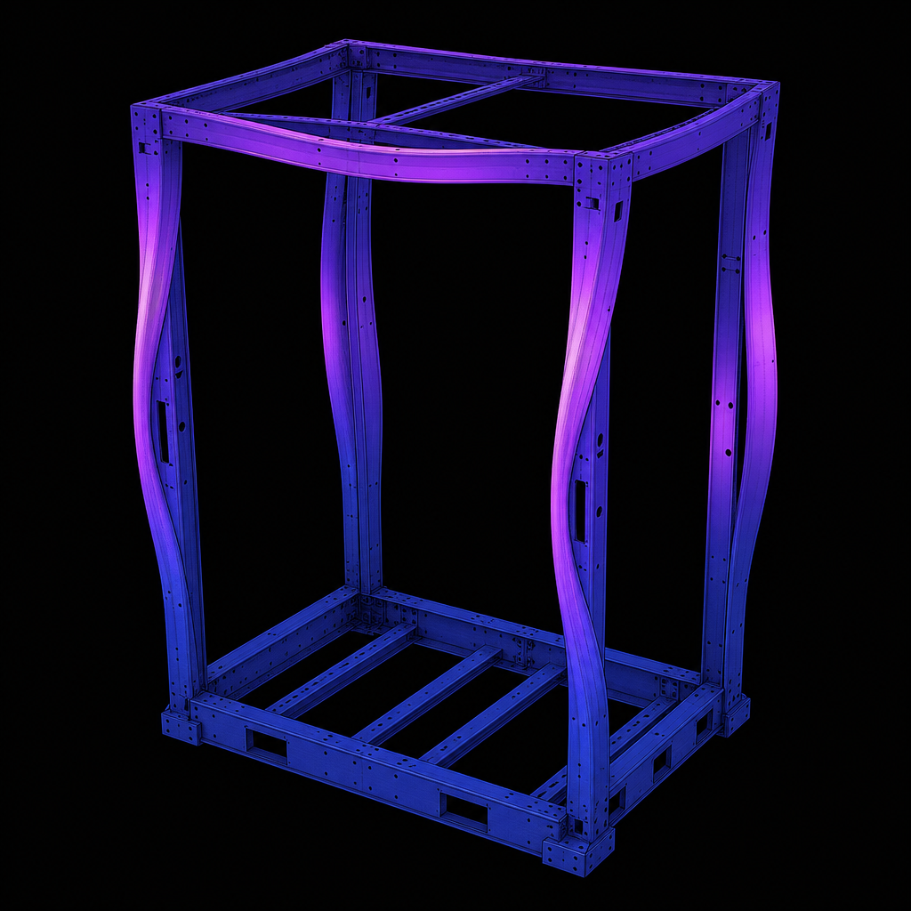
Buckling
-
Modal (demo Hz)
-

Seismic 0.4g
- Static FEA CLOSED TC-DEMO-CAB-FEA-061
- Modal / transport CLOSED TC-DEMO-CAB-MOD-061
- Prototype lift IN PROGRESS TC-DEMO-CAB-LIFT-061
- Drawing release FROZEN DWG-CAB-061-B
| Case | Max stress (demo) | Limit | SF | Status |
|---|---|---|---|---|
| Lifting | — | Allowable | ≥ 2.0 | Pass |
| Wind | — | Allowable | ≥ 1.5 | Pass |
| Transport | — | Allowable | ≥ 2.0 | Pass |
| Seismic 0.4g | — | Allowable | ≥ 1.5 | Pass |
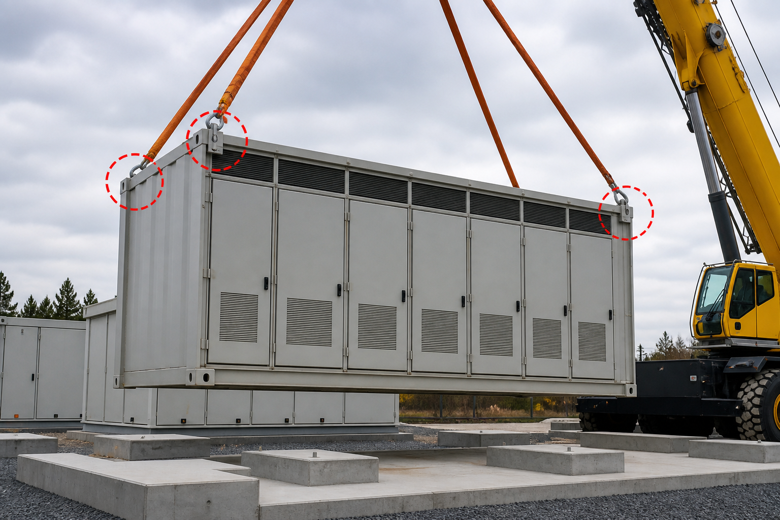
Lifting, stability and transport interfaces
Crane angle, center of gravity, road accelerations and base frame readiness · verified before shipment.
- Lift angle
- > 60° · SF ≥ 2.0 demo
- CG height
- 1120 mm demo · overturning SF ≥ 1.5
- Transport
- Vertical 1.0g · lateral demo envelope
- Base frame
- Anchor-ready · fork pockets optional
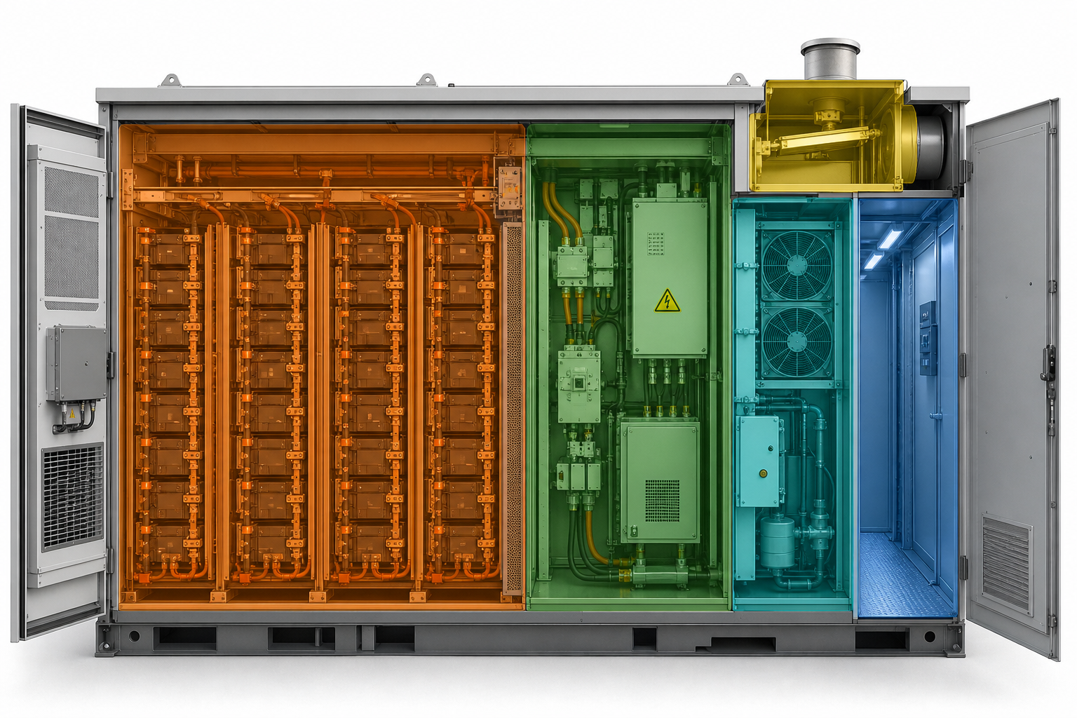
Functional zoning · structural implementation
Each zone is realized with physical isolation, access and interfaces — not color labels alone.
-
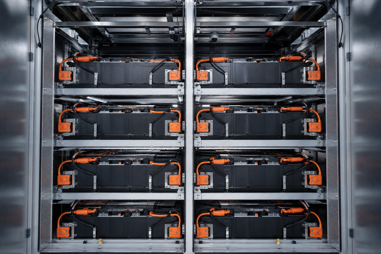
Battery zone
Racks · insulation · slide rails
-
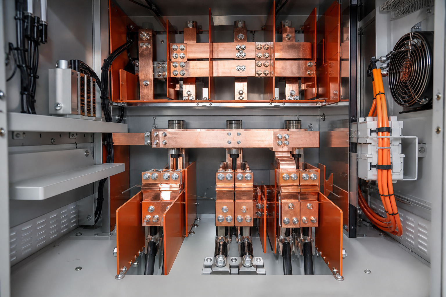
High-voltage zone
Busbars · barriers
-
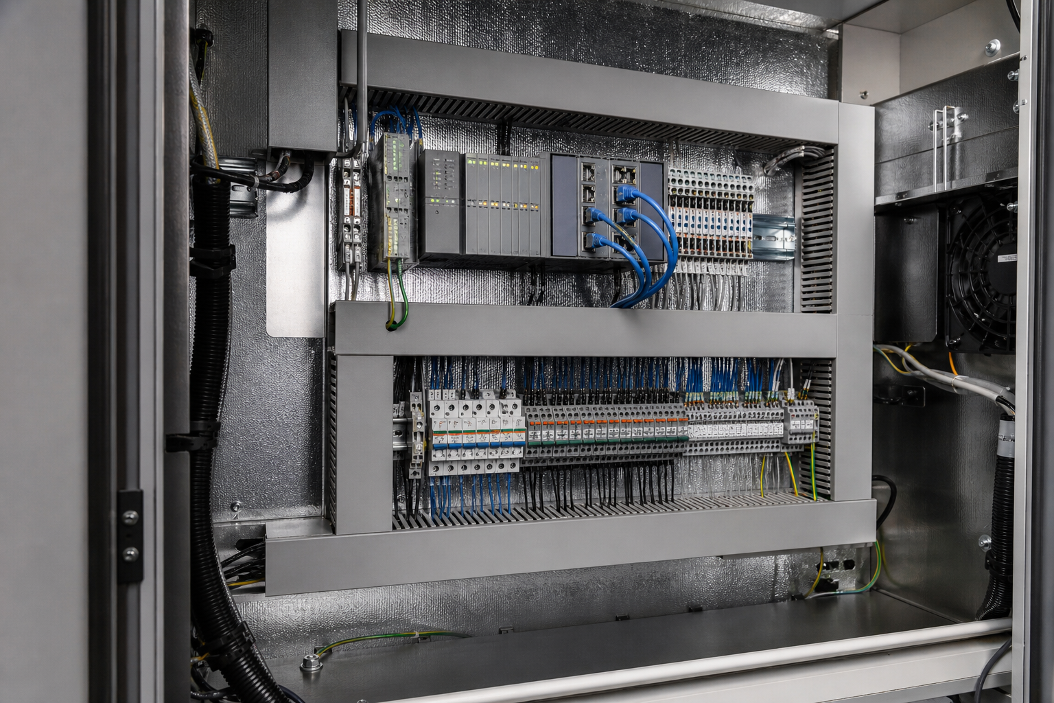
Control zone
LV · EMC shielding
-
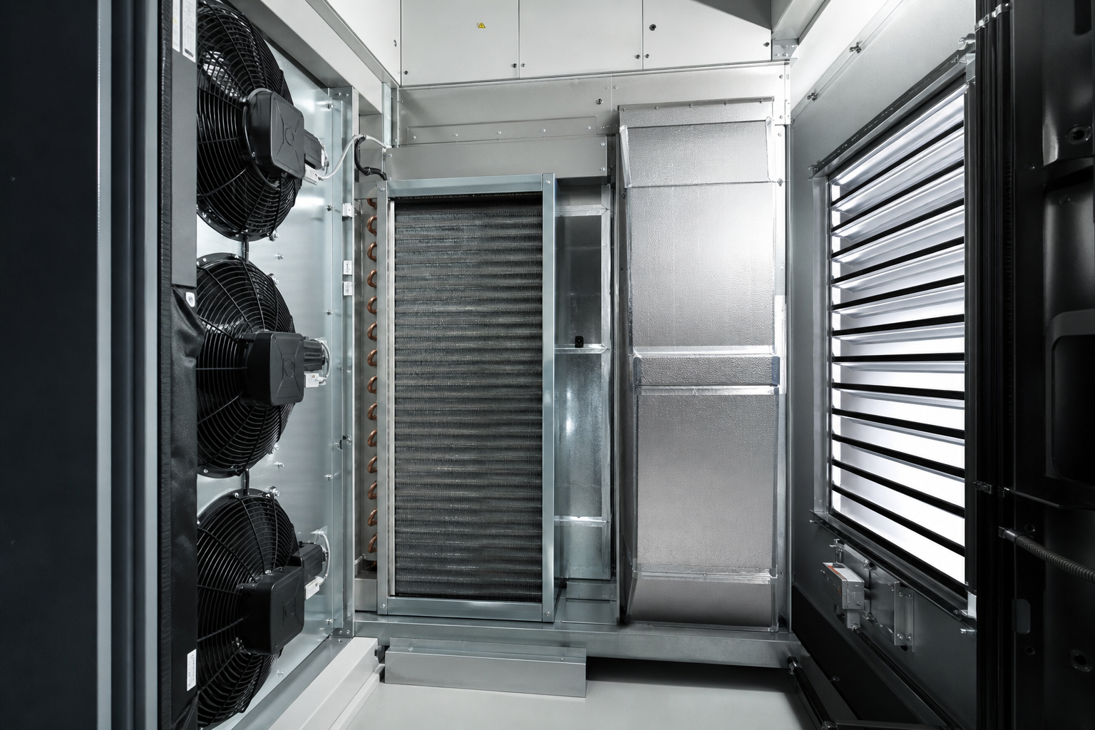
Thermal zone
Fans · airflow path
-

Fire & relief
Sensors · vents
-
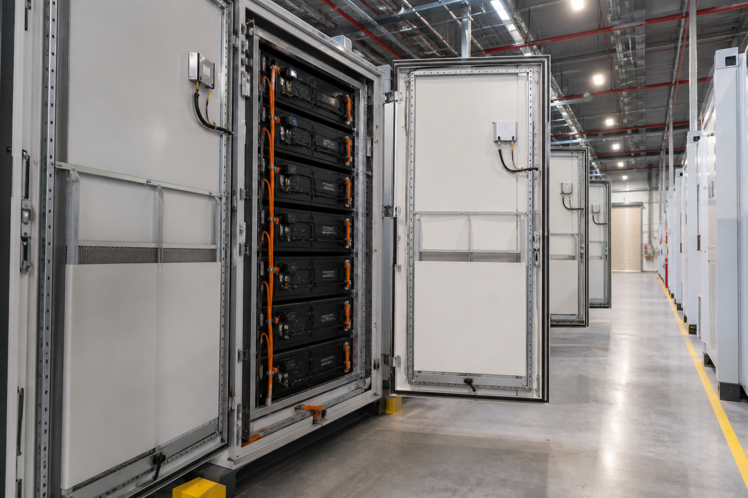
Service zone
Aisles · tool reach
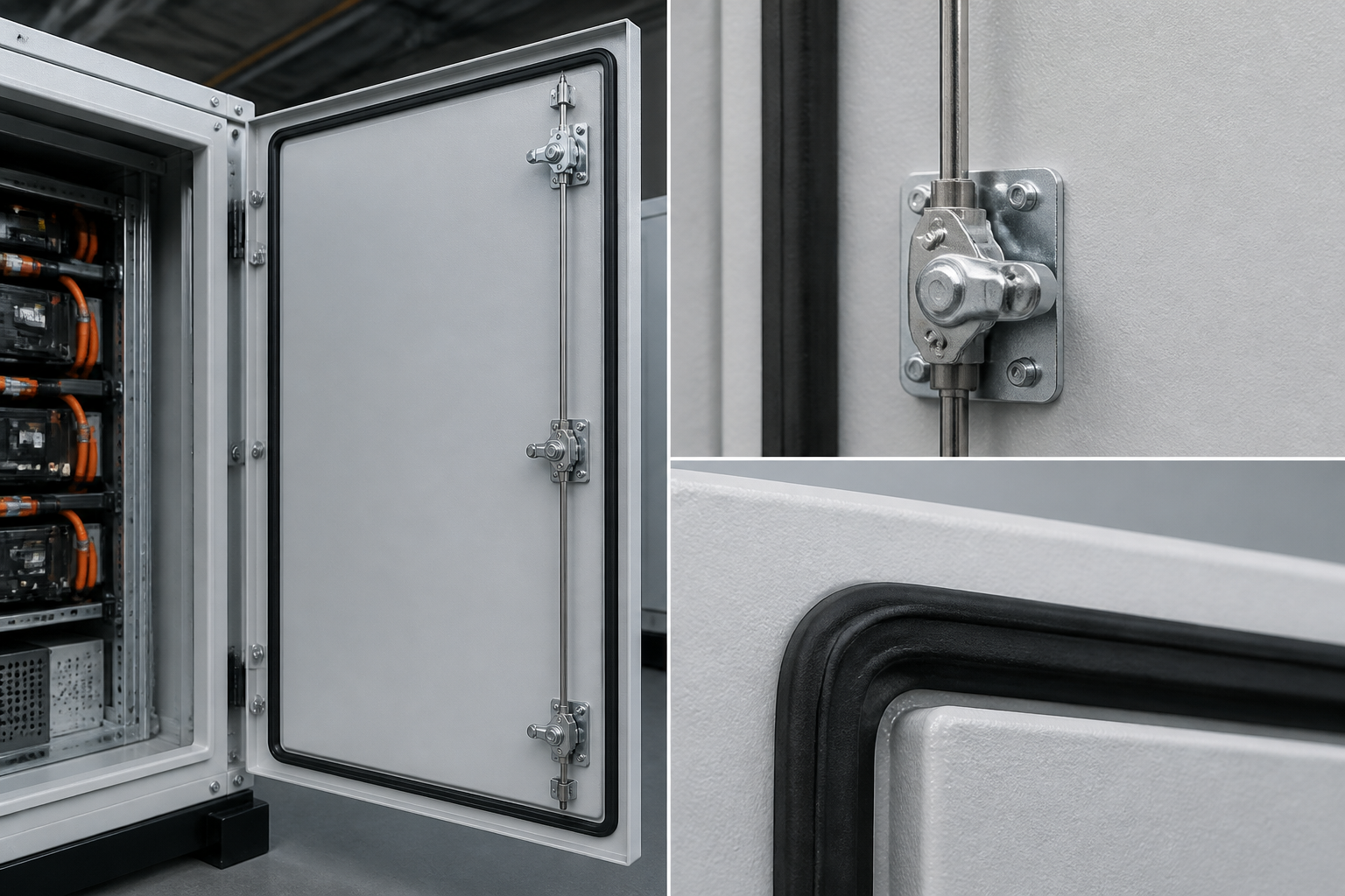
Doors, hardware, sealing and environmental protection
Gaskets, drains, coating interfaces, louvers, glands and equipotential bonding define protection · verified, not assumed.
- IP test plan PASS
IP54 cabinet · IP55 door demo protocol
- Door lock PASS
3-point latch · tool-key demo
- Triple seal PASS
Compression 20% ±5% demo
- Drain path PASS
Low-point drain · no cable tray crossing
- Coating interface REVIEW
C4/C5 touch-up at field weld · pending
- Equipotential ground PASS
Bonding map · door straps · PE bus demo
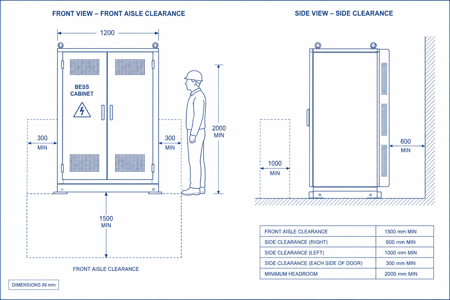
Human factors and maintainability
Clearances, pull-out strokes and operating envelopes keep service actions safe and repeatable.
- Front aisle
- > 900 mm demo
- Side / rear
- > 900 mm demo
- Fan drawer stroke
- ≥ 600 mm
- Reach radius
- 650 mm operating demo
- Internal lighting target > 300 lx demo
- Safety interlocks on energized compartments
- Tool access without removing structural members
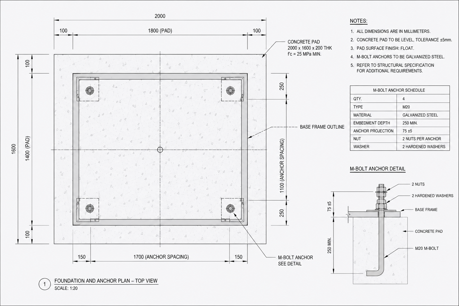
Foundation and anchor interface
Outdoor base requirements, flatness, drainage and anchor patterns complete the site structural interface.
| Item | Requirement (demo) |
|---|---|
| Concrete | C30 or above |
| Flatness | ≤ 3 mm / 2 m |
| Drainage slope | ≥ 1% |
| Anchors | M16–M30 × 4 pattern REV-C |
| Level precision | ≤ 1.0 mm horizontal demo |
Delivery outcomes and deliverables checklist
Released cabinet structure ships with load diagrams, anchor patterns, FEA summary and maintenance clearance map.
- Structure calculation summary REV-C REV-C
- General arrangement + section drawings GA pack
- Anchor / lift point diagram Interface
- FEA evidence pack Cases
- Maintenance access map Clearance
- BOM baseline Freeze