Integrated lithium battery energy storage solutions

BATTERY MODULE CONFIGURATION

Configuration modules that simultaneously satisfy electrical, structural, thermal and manufacturing boundaries

From cell selection, grouping and preload through busbar path, BMU sampling and cooling interface — verified against full-height Rack installation envelopes.

  • Cell & electrochemistry

    Cell & electrochemistry

    Form factor, lot match and OCV/ACIR windows

  • Structural constraints

    Structural constraints

    Preload, swelling gap and failure criteria

  • Electrical & control

    Electrical & control

    Busbar path, BMU sampling and isolation

  • Thermal & manufacturing

    Thermal & manufacturing

    Cooling interface, TIM and line capability

DEMO DATA · MOD-CFG-01 · 2026-W32

Engineering capabilities

  • Cell & electrochemistry

    Cell & grouping form

    Cell match, capacity, SOH consistency and grouping

  • Structural constraints

    Structure & interface control

    Stress, displacement, vibration and thermal expansion

  • Electrical & control

    Electrical & sensing

    Busbar, sampling, fuse, HVIL and closed-loop comms

  • Thermal & manufacturing

    Mechanism & manufacturing

    Fit, test, service, transport and tooling compatibility
Input constraint matrix (example)

ConstraintControl needKey params / rangeSource / note
CellMatched lot · OCV/ACIR window314 Ah LFP prismaticCell platform ICD
CoolingΔT ≤ 3 K @ 0.5CLiquid plate · TIM classThermal envelope
Protection350 A continuous · HVILFuse class demoHV interface ICD
Vibration8g / region templateTransport + seismic demoStructure load case
MaintenanceMax 1 cell reworkFront service · swap limitDFM gate
ManufacturingAuto torque · vision Poka-YokeMA-02 line capabilityPlant ICD
Pack / Rack fit4-point mount · ±0.5 mmBay 600×800×2260 mmRack envelope

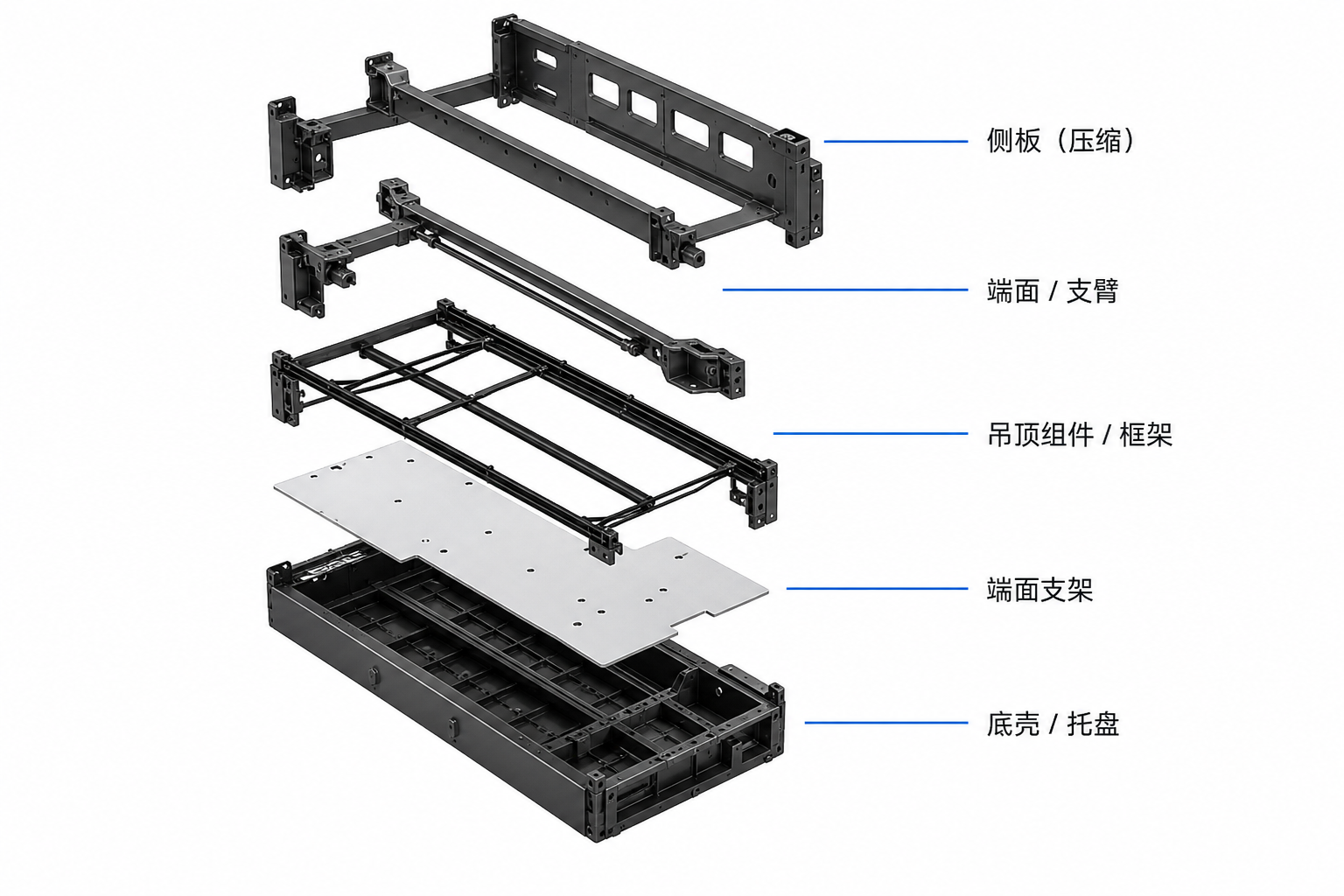
Module stack layers and interface control

Exploded stacking order and interface ICD keep cooling, HV/LV connectors and fix points consistent from prototype to Rack install.

  1. 01 Top cover / end plate
  2. 02 Side plate & stiffener
  3. 03 Insulation stack
  4. 04 Busbar & terminal
  5. 05 Cell group 1P24S
  6. 06 Preload pad / swelling gap
  7. 07 Cooling plate + TIM
  8. 08 BMU / AFE harness
  9. 09 HV / LV connectors
  10. 10 Guide pins & mounts
  11. 11 Seal & protective cover
  12. 12 Nameplate / traceability
Exploded module structure: side plates, end arms, frame, support, base tray
InterfaceControl itemModule response
Cooling pathPlate flatness · TIM classAl plate + TIM TC-DEMO-TIM-03
HV connector350 A · IP67 · HVILM12 busbar + HVIL demo
LV harnessBMU daisy-chain ≤ 8 m24-cell AFE chain REV-B
Fix points4-point mount · ±0.5 mmGuide pins + preload sensors

Key parts

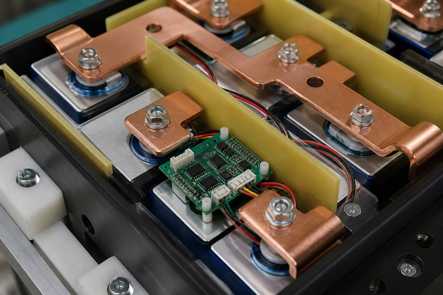
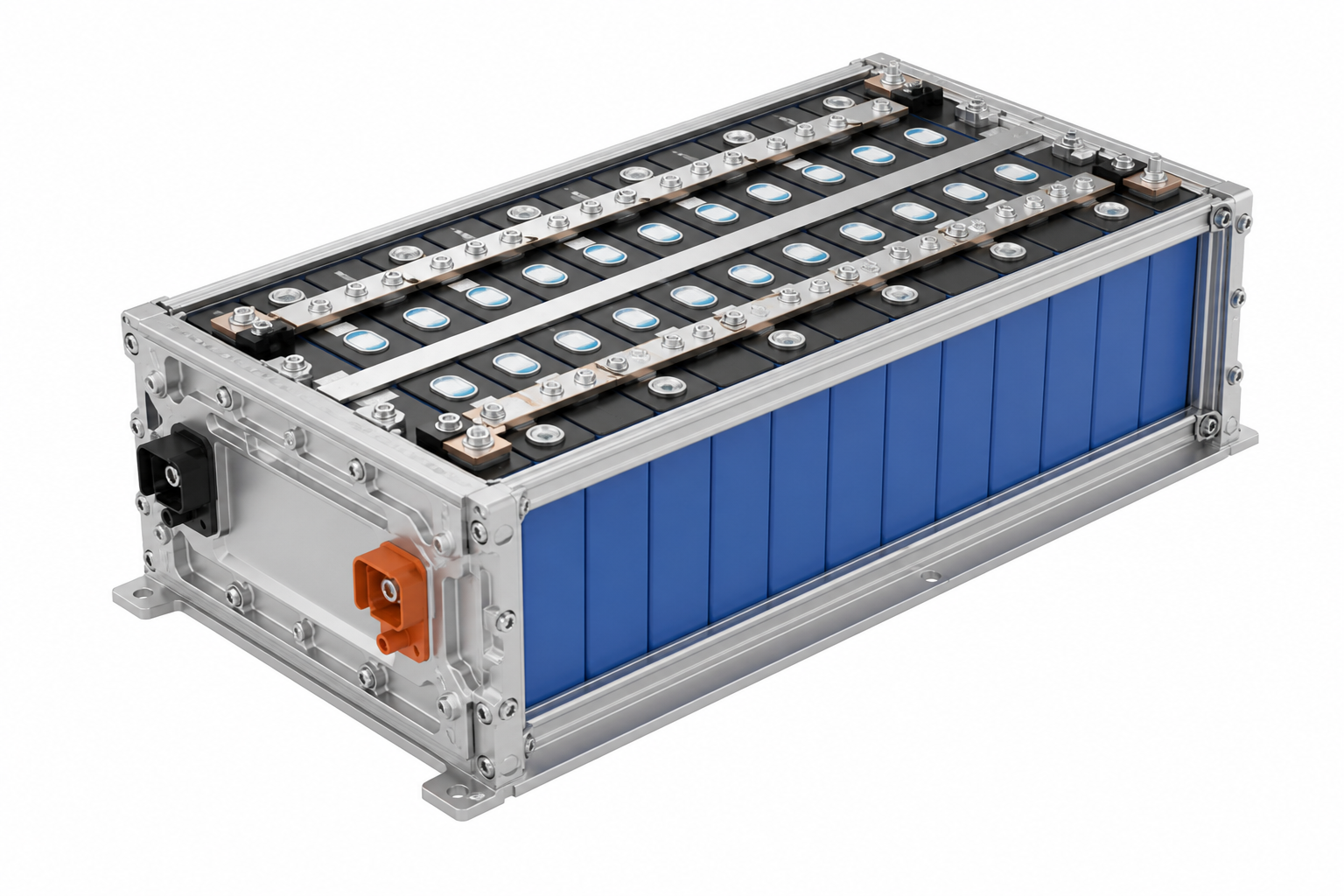
  • Busbar, insulation and BMU sampling detail Busbar & terminal detail
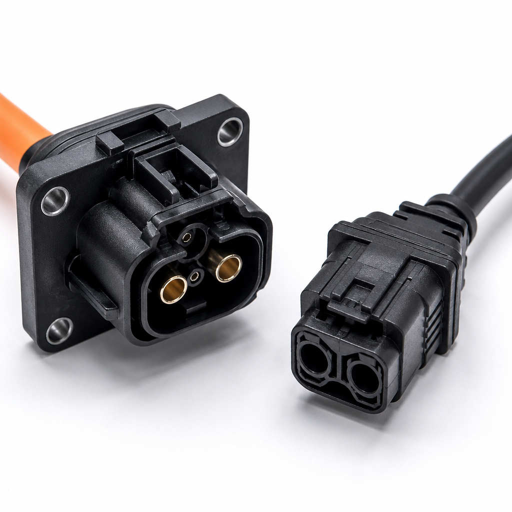
  • HV connector and HVIL interlock detail HV connector / HVIL
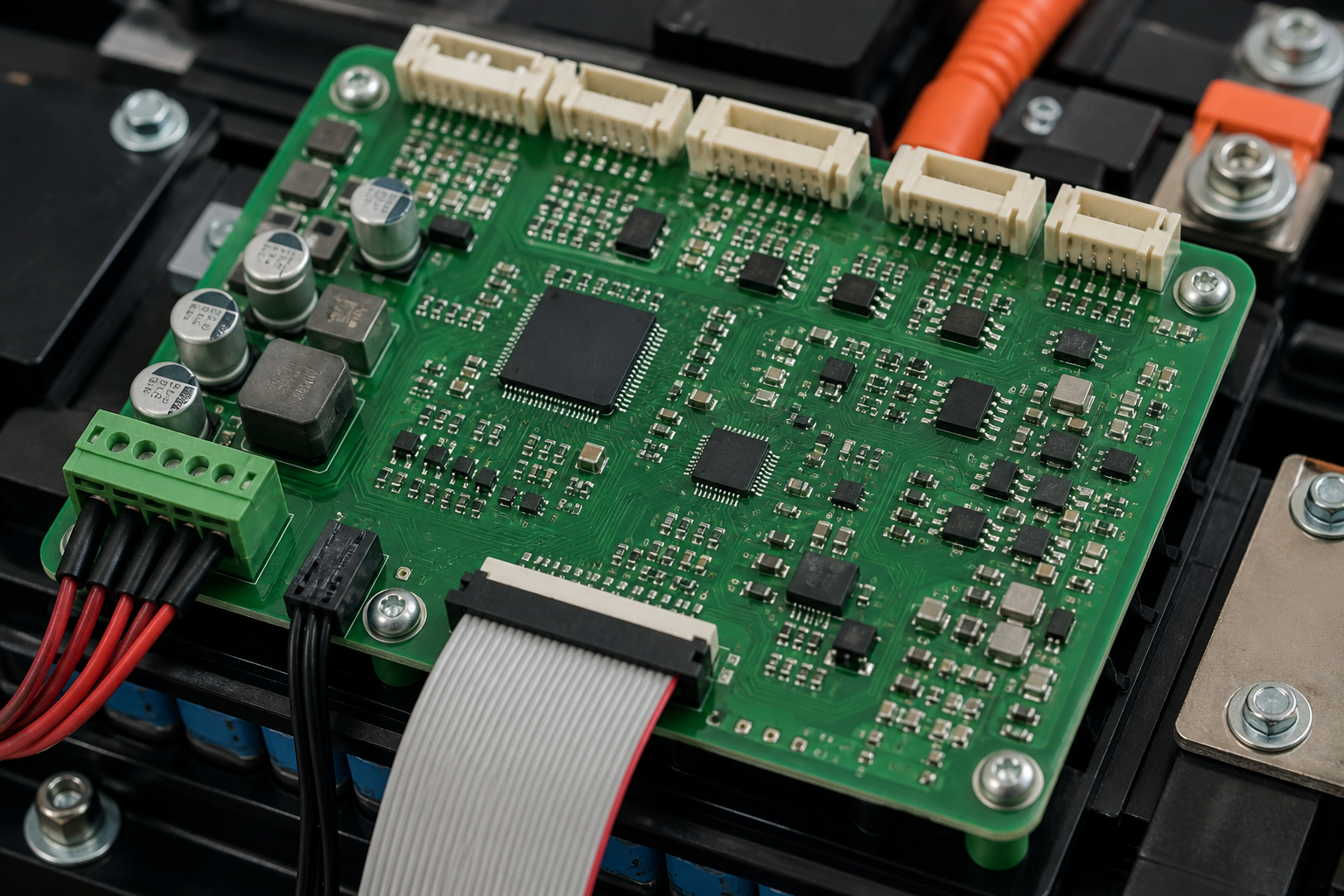
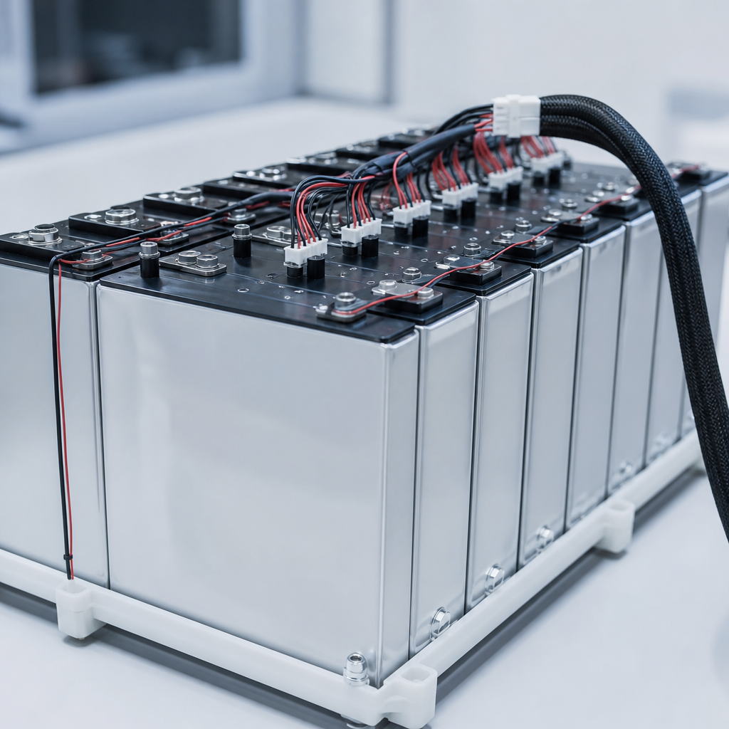
  • BMU sampling PCB and harness detail BMU / AFE sampling board

Module configuration is not cell arrangement — it is the shared boundary of electrical, structural, thermal and sensing paths

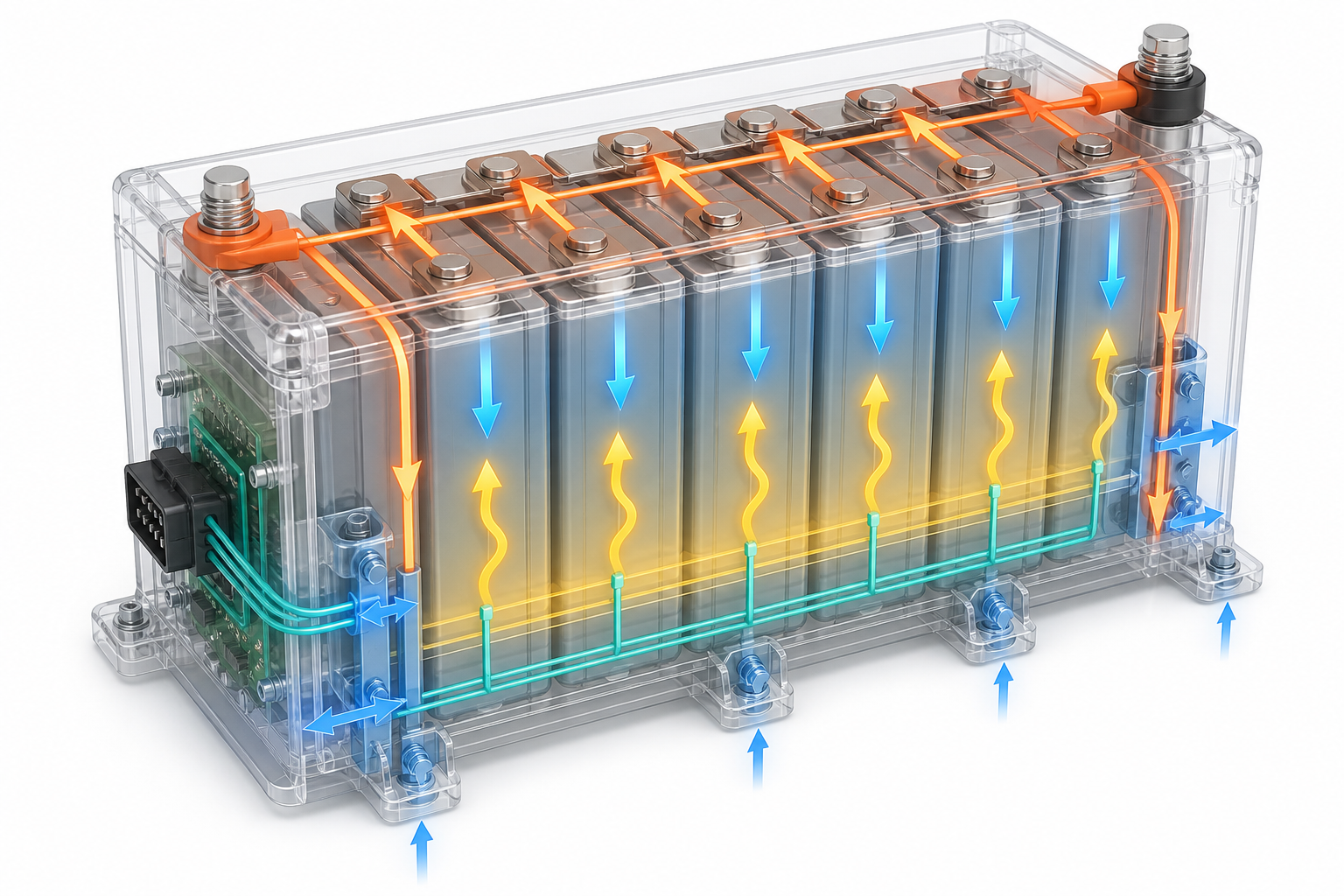
Multi-physics current, force, heat and signal paths on a module
  • Current path
  • Compression / force path
  • Heat path
  • Sensing network
  • Vent / relief path
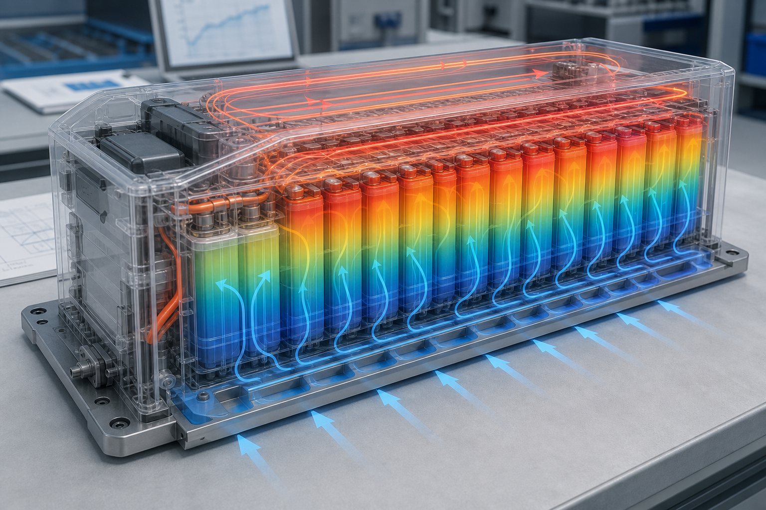
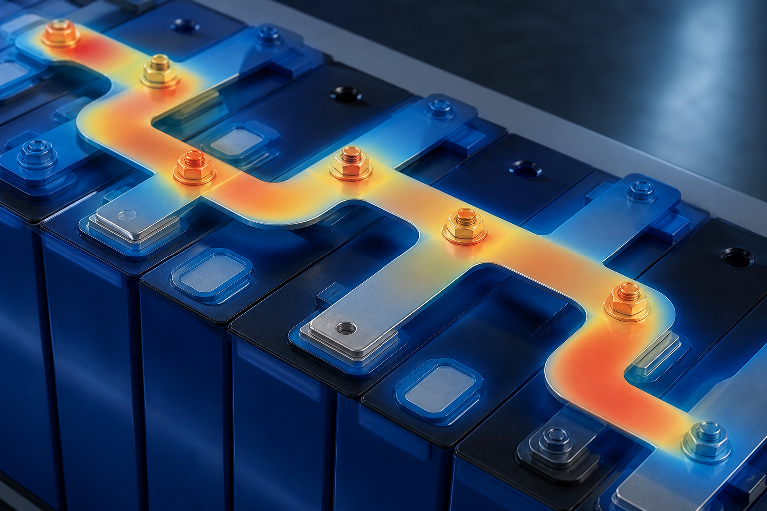
  • Module thermal path and heat-map visualization Thermal uniformity ΔT ≤ 4.3 ℃
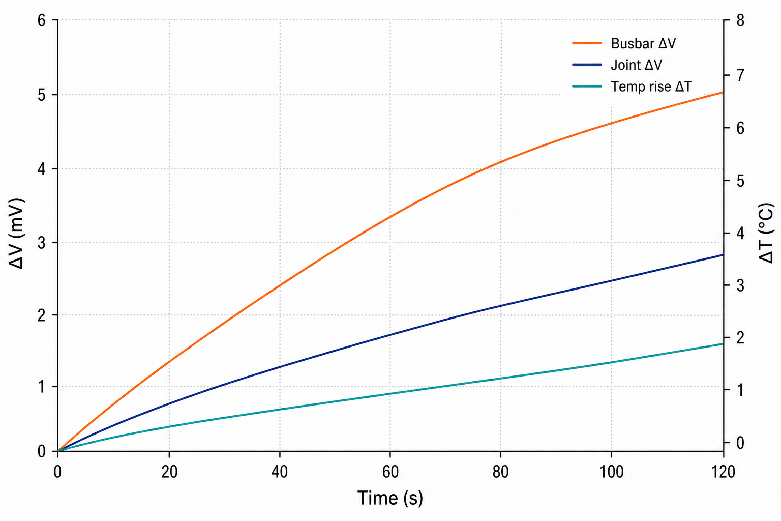
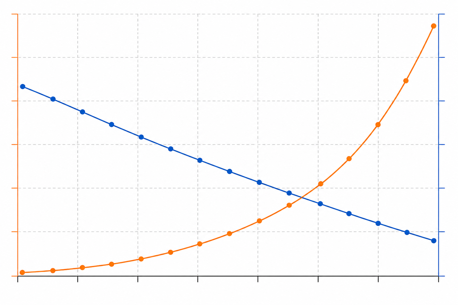
  • Busbar voltage-drop and temperature-rise curves Voltage drop (@400A) ≤ 3.8 mV
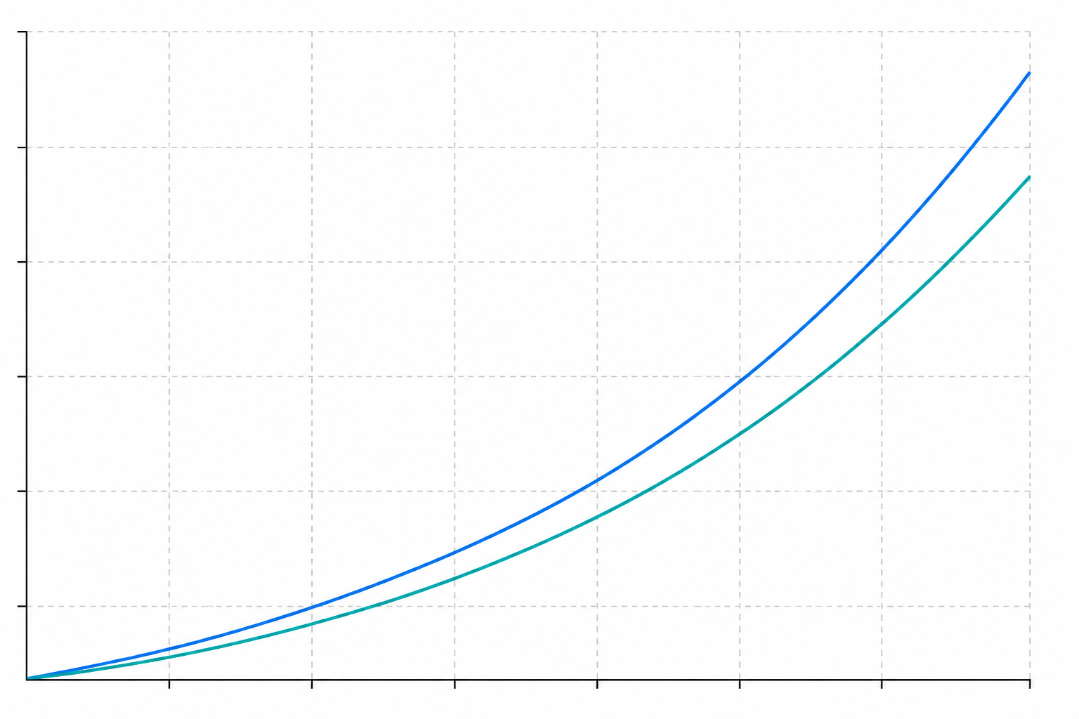
  • Preload force versus displacement curve Preload range 10–22 kN
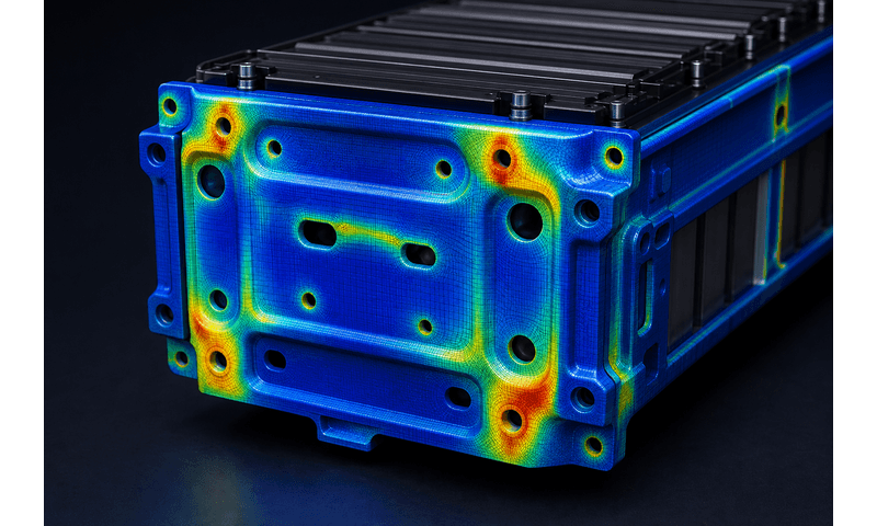
Structural FEA stress heatmap on module frame

Cell application plan comparison and decision

Candidate groupings are scored against electrical, structural, thermal and manufacturability gates before DV freeze.
Plan A · Horizontal

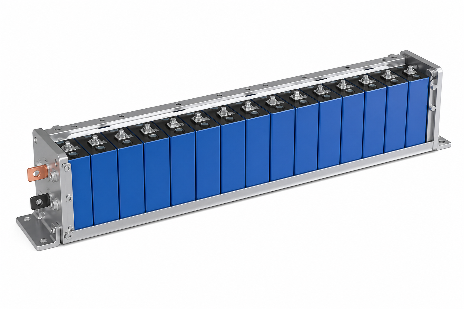
Plan A single-row horizontal module layout
Grouping
1P20S
Nom. V
64.0 V
ΔT
≤ 3.5 K
DFM
Review

Plan B · Stacked (selected)

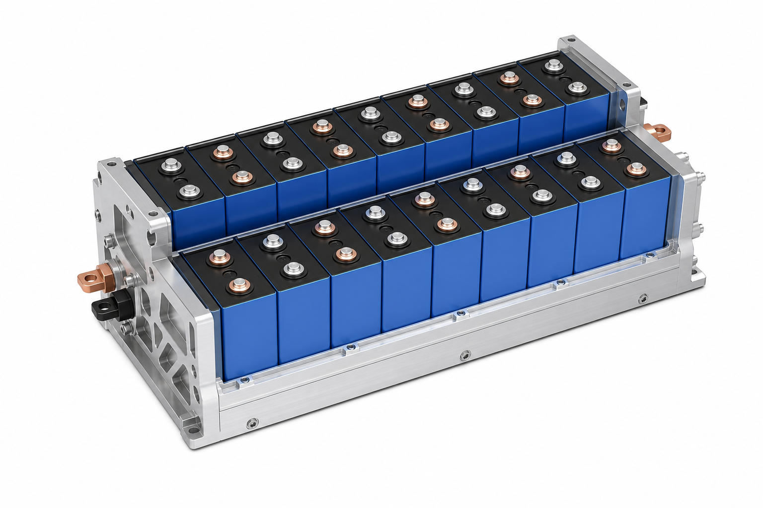
Plan B double-row offset module layout
Grouping
1P24S
Nom. V
76.8 V
ΔT
≤ 3.0 K
DFM
Pass

Plan C · Vertical

Plan C double-row side-by-side module layout
Grouping
1P28S
Nom. V
89.6 V
ΔT
≤ 4.0 K
DFM
Fail height

Structural preload and mechanical boundaries

Grouping topology, preload strategy and Rack fit determine contact resistance, swelling accommodation and serviceability.

  • Structure composition

    • End — side — cells — pad order
    • Insulation stack locked
    • Guide pins before preload
    Exploded module structure: side plates, end arms, frame, support, base tray
  • Preload curve

    • 120 kN ± 5 kN window
    • Creep monitor demo
    • Displacement vs force log
    Preload force versus displacement curve
  • Force path

    • End-plate load path
    • Swelling gap 4.2 mm
    • No shell warp at peak
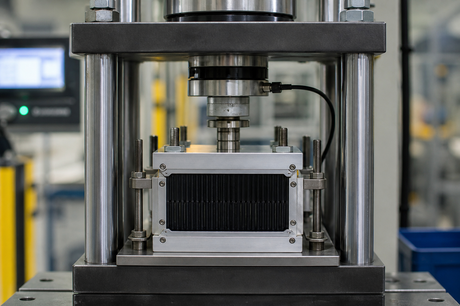
    Hydraulic preload press with load-cell logging
  • Structural FEA

    • 8g transport + seismic
    • Primary stress path
    • Hot-spot stress ≤ limit
    Structural FEA stress heatmap on module frame
  • Tolerance table

    • 4-point mount ±0.5 mm
    • Guide-pin Ø demo
    • Bay envelope check
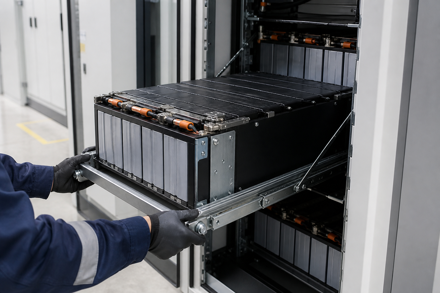
    Module insertion into full-height Rack bay

Busbar, terminals and insulation engineering

  • Busbar design

    • Temp gradient @400 A
    • J ≤ 5.2 / 5.0 / 4.8 A/mm²
    • Meets ≤ 6 A/mm² target
    Busbar current-density and temperature-rise view
  • ΔV & temperature rise

    • ΔV ≤ 5.8 mV @400 A
    • ΔT @400 A ≤ 6.5 °C
    Busbar voltage-drop and temperature-rise curves
  • Insulation & safety

    • Creepage ≥ 8 mm · clearance ≥ 6 mm
    • Hipot 4000 VDC / 60 s
    • IR ≥ 1000 MΩ
    • PBT/PC + GF
    Busbar, insulation and BMU sampling detail
  • Mating & interlock

    • Contacts 500 V / 500 A
    • HVIL interlock · plug-in
    HV connector and HVIL interlock detail
  • Insertion & service disconnect

    • Guided insertion float
    • Disconnect / fault protect
    • Service hand-feel
    Module tray service disconnect from Rack

BMU sampling and sensing coverage

  • Cell voltage sense

    • 52 cells in series
    • Sense accuracy ≤ ±1 mV
    • Diff / common-mode sense
    Cell voltage sense taps on series prismatic cells
  • Temperature sense

    • NTC × 8 (cover / cold plate)
    • Accuracy ≤ 0.5 °C
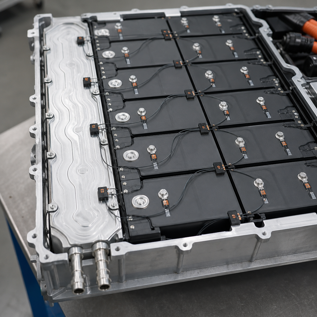
    NTC temperature sensors on module cover and cold plate
  • Current & interface signals

    • 400 A Hall current
    • Interface self-check
    • Door / heat / harness
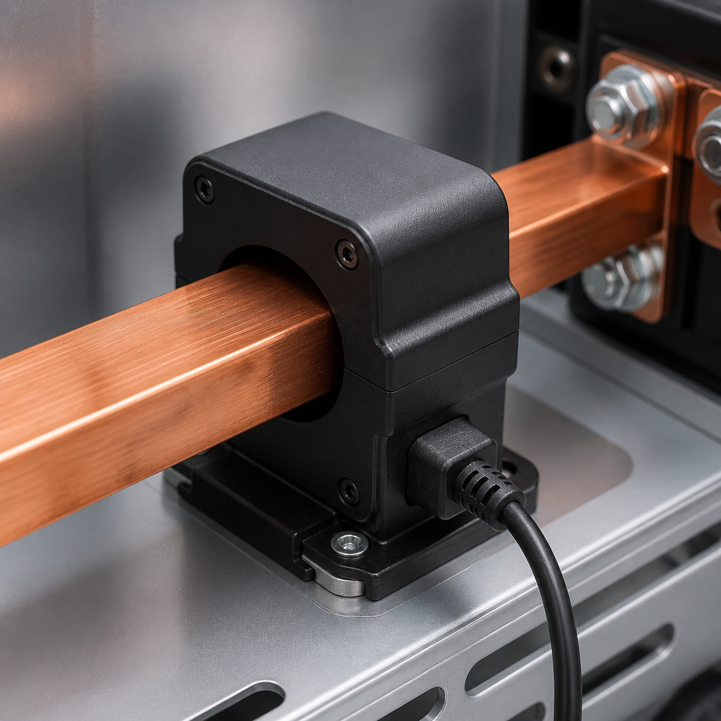
    Hall current sensor on module busbar
  • BMU module

    • MCU + AFE
    • Low self-discharge
    • High-reliability link

    BMU sampling PCB and harness detail
  • Harness & EMC

    • Shielded routing
    • Zoned wiring
    • Star ground
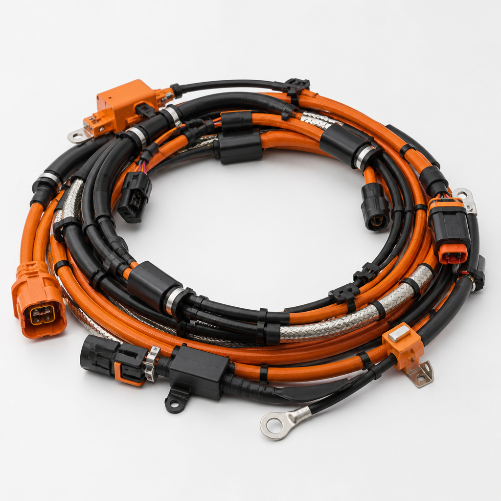
    Shielded HV harness with EMC ferrites
  • Cabinet BMS

    • CAN FD / 1 Mbps
    • Container redundancy
    • Over-current / short
    BMS modules inside a control cabinet

Thermal management & interface engineering

  • Cold-plate design (baseline)

    • Parallel dual circuits
    • Auto channel topology
    • ΔP ≤ 60 kPa
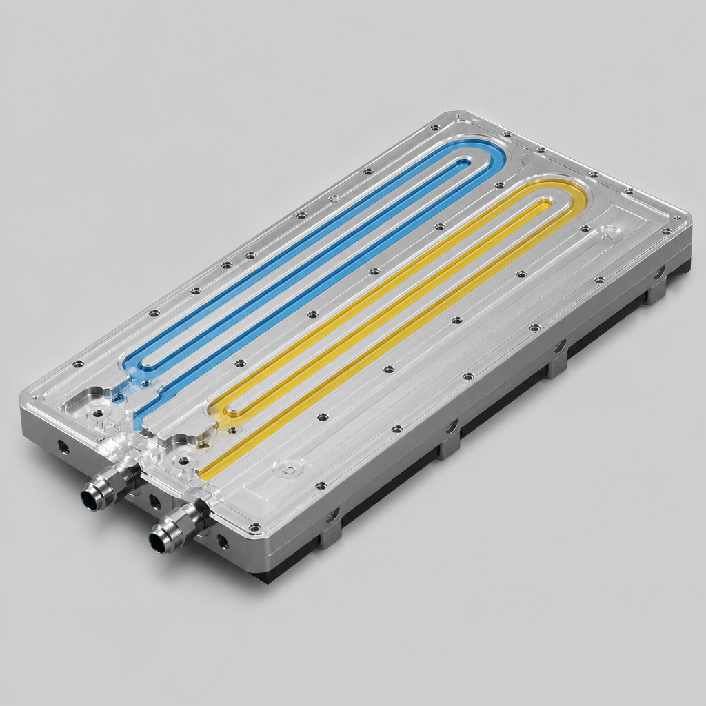
    Aluminum liquid cooling plate with dual flow channels
  • Uniformity & hotspots

    • ΔT ≤ 5.0 °C
    Module thermal path and heat-map visualization
  • TIM & contact

    • TIM pad 1.5 mm
    • Contact R_th ≤ 0.12 K·cm²/W
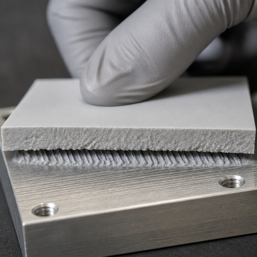
    Thermal interface TIM pad contact on cold plate
  • ΔP & flow

    • ΔP ≤ 60 kPa
    • Flow ≥ 15 L/min
    Coolant pressure-drop and flow curves
  • Coolant boundary & seal

    • Inlet dew point ≥ 10 °C
    • Seal / barrier layer
    • Relief / drain
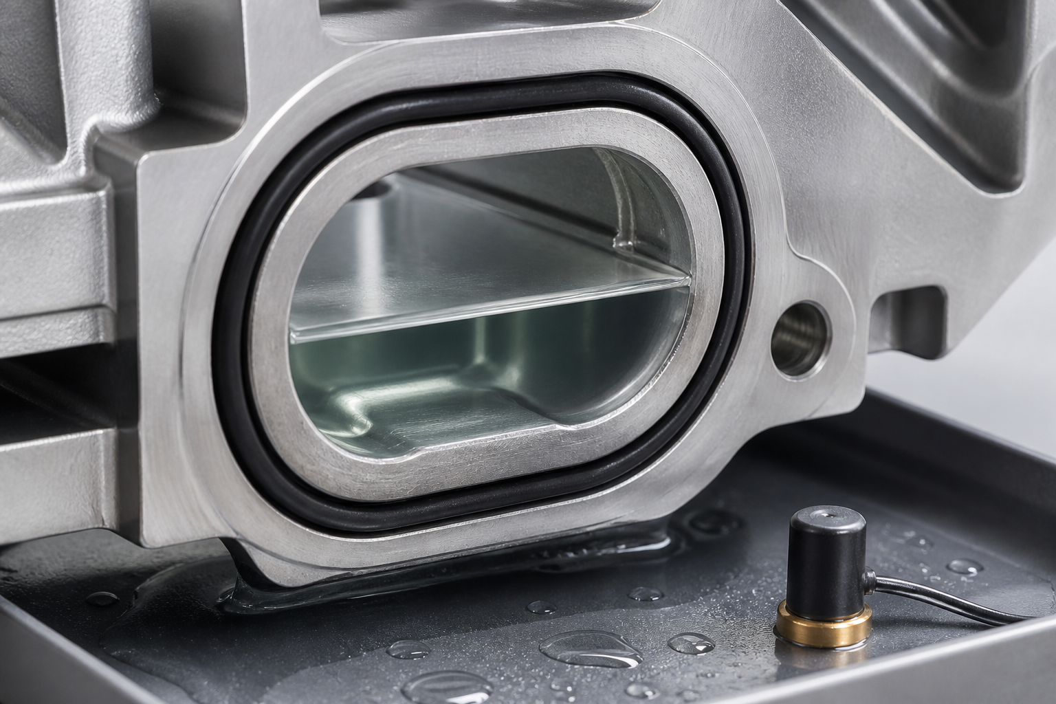
    Cold-plate seal and coolant boundary detail
  • Quick connect / disconnect

    • DN12 path
    • Inlet / vent valves
    • Fault-lock sensing
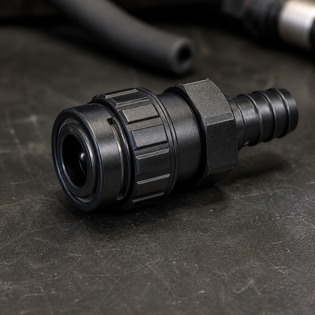
    DN12 liquid quick-connect coupling

The same module must fit Rack space, tooling capability and maintenance motions
Custom modules must be buildable at rate, installable in full-height bays, and serviceable via front maintenance — tooling and vision gates are part of the configuration.

  1. Module sliding into Rack bay envelope
    Rack bay insert

  2. HV/LV harness mating in Rack bay

    HV/LV harness mate

  3. Mounting bolt torque window on Rack rail

    Mount torque window

  4. Front-service withdrawal clearance check

    Service withdrawal gap

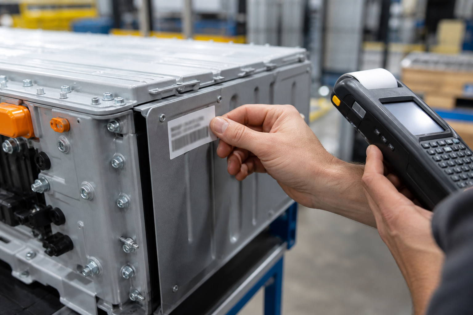
  5. Traceability nameplate and serial bind

    Traceability bind

Design for manufacture & service (DFM/DFA & Poka-yoke)

From part orientation and torque windows to vision gates — manufacturability and serviceability are written into the module configuration.

  • Bottom-tray adhesive dispense for module Tray adhesive
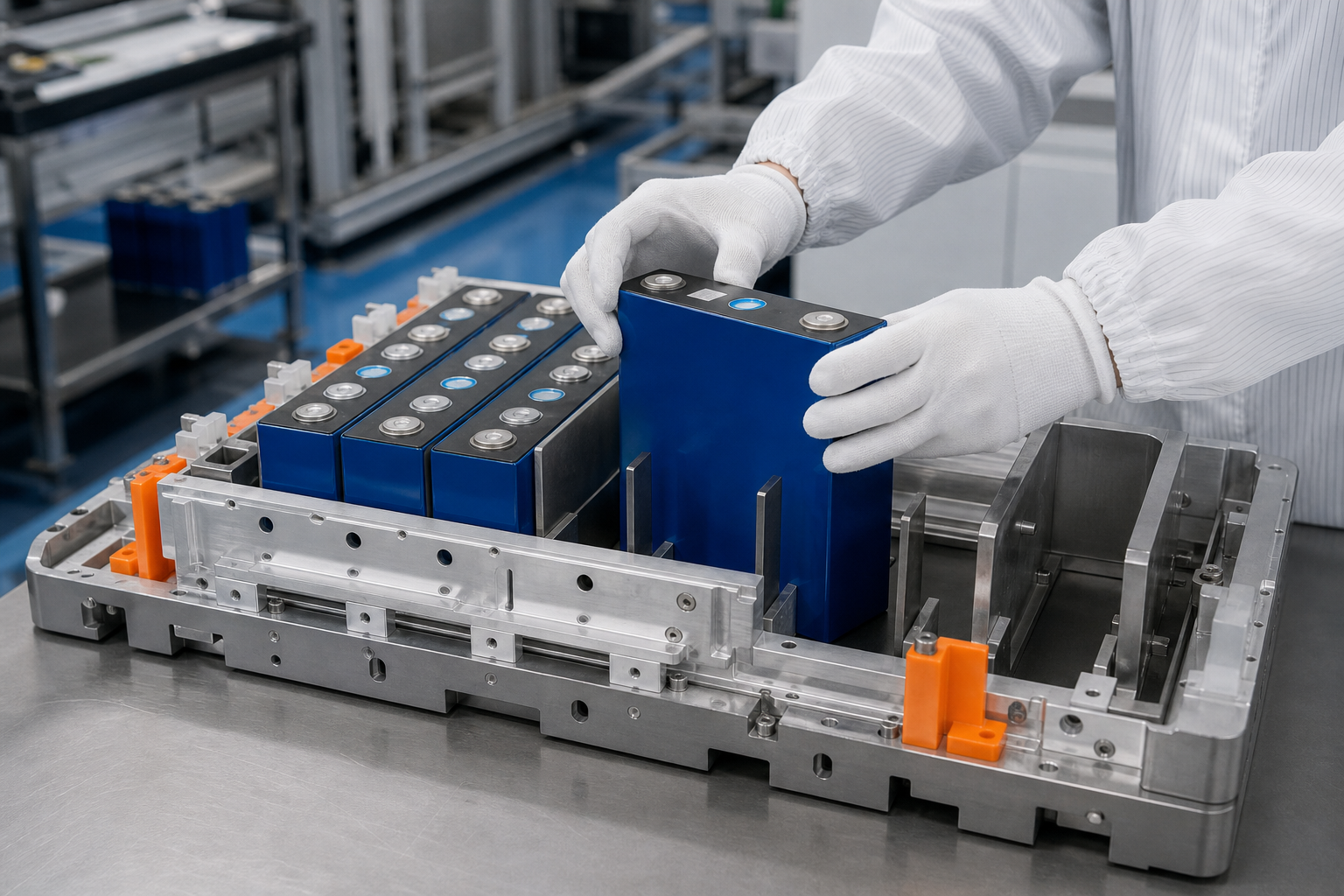
  • Prismatic cell stacking into module fixture Cell stacking
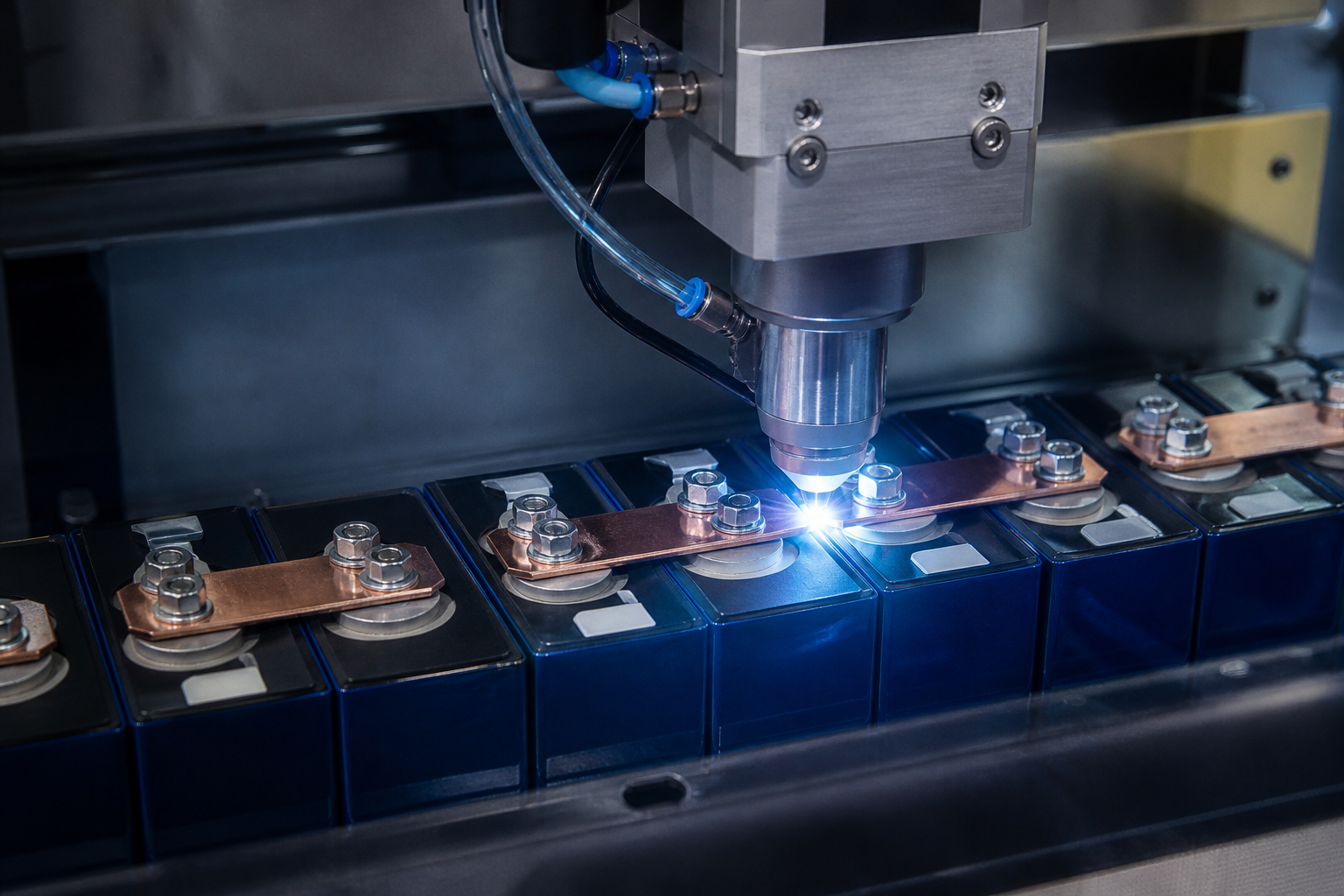
  • Laser welding copper busbars to cell terminals Busbar weld
  • Hydraulic preload press with load-cell logging Preload press
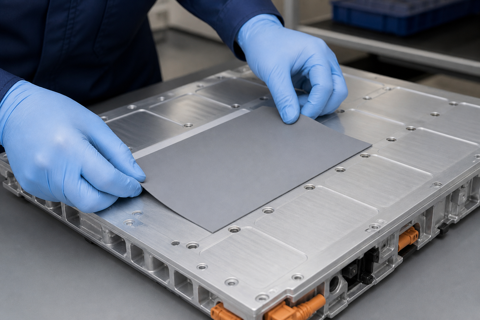
  • TIM pad application on cold plate TIM apply
  • Vision / EOL visual inspection of module Vision gate
  • DFM poka-yoke assembly gesture detail Poka-yoke

DFMEA

Failure modeEffectSev.DetectionControl
Cell polarity reversedShort / no power-up10Vision gatePolarity color + barcode recipe interlock
Busbar orientation wrongIR exceed / local heat8Vision + torqueGuide pins + ±10% torque window
Preload under/overContact drift / shell warp9Sensor120 kN ± 5 kN · logged per unit
TIM miss / bubbleΔT exceed7Thermal EOLApply fixture + EOL thermal scan
Sense wire openSOC / protection blind9EOL electricalAFE self-check · missing channel block
HV connector mis-mateHVIL open / no power-up9Interlock + barcodeKeyed HVIL + recipe match on MA-02
Wrong / missing nameplateTraceability break6Vision + MESOCR gate · serial bind before EOL release

Validation plan | Key tests

Validation planKey testStatus
Module EOL electrical Hipot 4.5 kV / 60 s · IR > 1 GΩ Closed
Busbar & IR drop ΔV @ 400 A · temp rise map Closed
Thermal uniformity ΔT map @ 0.5C continuous In progress
Vibration / shock Random 1.0 g · 30 g / 11 ms In progress
IP / seal IP54 demo · leak check Planned
Rack bay fit 4-point mount · guide-pin gauge Planned
Function / comms Bus / I/O · AFE channel self-check In progress

Prototype verification evidence (key test snapshots)

  • Hipot

    4.5 kV / 60 s pass

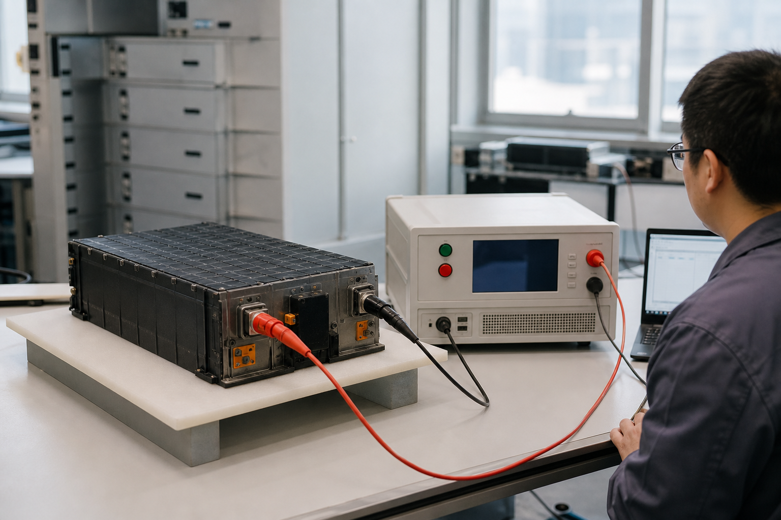
    Dielectric hipot withstand test on module terminals
  • Insulation

    > 1 GΩ @ 1000 V

    Busbar, insulation and BMU sampling detail
  • IR drop

    3.6 mV @ 400 A

    Busbar voltage-drop and temperature-rise curves
  • Thermal map

    ΔT ≈ 3.7 °C

    Module thermal path and heat-map visualization
  • Vibration

    Random 1.0 g pass

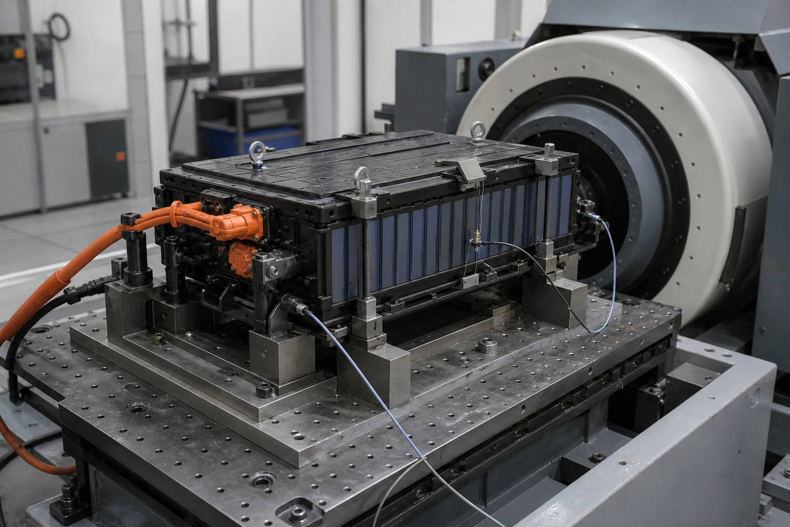
    Module on electrodynamic vibration shaker
  • Shock

    30 g / 11 ms pass

    Structural FEA stress heatmap on module frame
  • ESD

    Contact / ±8 kV pass

    BMU sampling PCB and harness detail
  • IP / seal

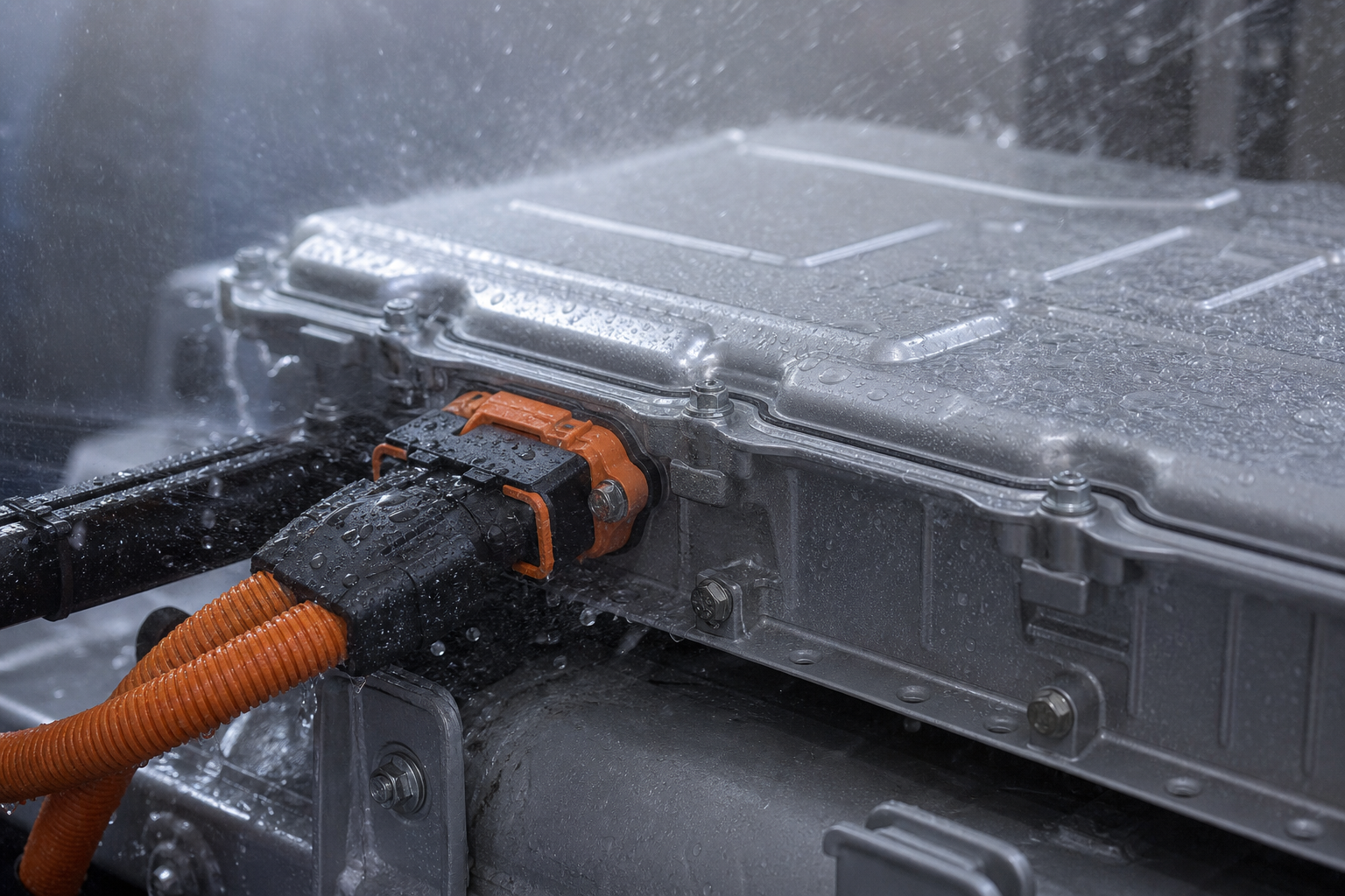
    IP54 demo pass

    IP54 seal and spray demonstration on module enclosure
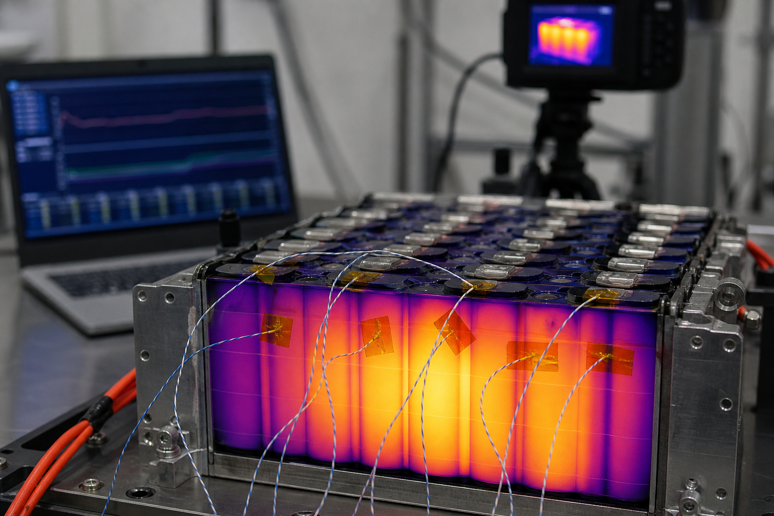
  • Internal ΔT

    180 min / ΔT ≤ 7 °C

    Internal temperature-rise test with thermocouples
  • Function

    Bus / I/O OK

    EOL functional and Bus / I/O communication test
Battery factory campus at night

Design freeze and controlled delivery

Freeze drawings, BOM, torque windows and interface ICD — then enter OEM & ODM collaboration with a manufacturable control plan.

  • Module configuration matrix REV-B
  • Busbar / insulation drawings
  • BMU channel map and calibration
  • Thermal interface specification
  • DFM / DFMEA summary
  • Prototype verification summary