










Communication Protocol|ICD engineering
From interface definition to anomaly recovery — make the system truly interoperate
Protocol customization covers physical interfaces, message semantics, timing, exception recovery and version compatibility across BMS, PCS, EMS, fire, metering and customer SCADA.
Sample message Demo data
- Signal
- MaxChargePower
- ID
- 0x18FF50E5
- Value
- 320.5 kW
- Quality
- GOOD
-

Endpoints & roles
Ownership, authority and control priority.
-

Unified signal dictionary
Names, units, scale and quality flags.
-

State & command handshake
Observable, controllable, verifiable.
-

Anomaly recovery & joint verification
Defined degrade paths and staged prove-out.
Device boundaries & role map
Role band plus control-priority ladder — one ICD owns who may override whom Demo data
- BMS Limits · contactors · 0x1xxx
- PCS Power · grid codes · 0x2xxx
- EMS Schedule · setpoints
- HVAC Thermal aux links
- Fire Dry contact + CAN
- Meter Energy / PQ tags
- Gateway Protocol bridge
- Tool Service · audited
Line legend
- CAN FD Control / high rate
- RS485 Aux / meter
- Ethernet Northbound
- Hardwire E-stop / HVIL
Control authority & priority
| Authority | Priority | May override |
|---|---|---|
| Safety / E-stop | P0 · highest | All power & contactor paths |
| BMS protection | P1 · high | SOP clamps · local trip |
| EMS schedule | P2 · medium | P/Q setpoints within band |
| Field tool | P3 · low | Engineer mode · audited |
Layered communication architecture
Physical → link → application → channel mapping — media changes must not rewrite semantics
- Physical Connectors, cable class, isolation
- M12 / Phoenix
- Shield & drain
- Galvanic isolation
- Link Frames, addressing, media access
- CAN FD · Modbus
- IEC 61850 option
- VLAN / baud / term
- Application Signals, units, quality
- Endian fixed
- Scale / offset / enum
- Severity flags
- Channel map Example bindings
- BMS↔PCS CAN FD
- EMS Modbus TCP
- Fire dry+CAN
End-to-end trace
Signal end-to-end traceability — eight steps
From connector pin to system action and event log · demo fields Demo data
- Physical port M12 pin · shield bond
- Channel CAN FD ID / Modbus addr
- Frame Byte / bit layout
- Parse Type · scale · unit
- Semantics Named control point
- Handshake State · command pair
- System action PCS / contactor / EMS
- Event log Stamp · quality · severity
Unified signal dictionary
Master table plus CAN FD message sidebar · demo Demo data
| Signal | Src→Dst | Type | Unit / scale | Rate | Quality | Severity |
|---|---|---|---|---|---|---|
| PackV_Avg | BMS→EMS | UINT16 | 0.1 V | 100 ms | GOOD | Info |
| PackI_Hall | BMS→PCS | INT16 | 0.1 A | 20 ms | GOOD | Info |
| SOP_Charge | BMS→EMS | UINT16 | 0.1 kW | 200 ms | GOOD | Warn |
| PCS_P_Cmd | EMS→PCS | INT16 | 0.1 kW | 100 ms | GOOD | Info |
| FaultWord_BMS | BMS→EMS | BITFIELD | — | 50 ms | STALE | Warn |
| EStop_Fb | Safety→All | BOOL | — | Hard+CAN | GOOD | Crit |
State & command handshake matrix
Who may start, stop, clear faults or override — encoded in one matrix Demo data
| BMS state | PCS | EMS command | ACK | Result |
|---|---|---|---|---|
| OFF | OFF | StartSelfCheck | Yes | Enter SELF-CHECK |
| STANDBY | STANDBY | Precharge | Yes | PRECHARGE |
| READY | READY | Charge | Yes | CHARGE |
| FAULT | ANY | PowerOn | No | Forbidden |
| READY | DERATE | Discharge | Cond. | SOP clamp |
| ESTOP | TRIP | Reset | Cond. | Role + audit |
Forbidden transitions
- FAULT → PowerOn without clear
- ESTOP → RUN without latch reset
- Dual writers on same setpoint
- Allowed
- Conditional
- Forbidden
Time & data-quality engineering
Four cards — trigger, quality policy, time sync, reliability
Trigger mechanism
- Cyclic
- Per ICD rate
- Event
- On change / edge
- Polled
- Master request
- Burst
- Fault dump demo
Quality codes & policy
- GOOD
- Within rate window
- STALE
- Hold last · alarm
- INVALID
- Parse / logic fail
- OOR
- Outside ICD limits
Time sync
- Clock
- NTP / PTP demo
- Seq ID
- Monotonic / link
- Stamp
- Source + gateway
- Order
- Cmd before confirm
Message reliability
- CRC
- Frame / PDU
- Rolling cnt
- Replay detect
- Heartbeat
- 500 ms · 3 miss
- Auth tier
- Write gated
Deterministic anomaly behavior
Anomaly communication — defined degrade, alarm and recovery
Lost links and conflicts never become ad-hoc operator guesses Demo data
| Anomaly | Detect | Degrade / safe action | Alarm & recovery |
|---|---|---|---|
| Link timeout | 3× · 500 ms | Hold last → safe stop | Re-handshake + audit |
| Heartbeat loss | Watchdog | PCS stop · EMS alarm | Manual clear gated |
| Command conflict | Dual writers | Reject · keep prior | Role arbitration |
| Version mismatch | ICD hash fail | Read-only · block control | Align ICD + retest |
Alarm & fault mapping
Source codes map to severity, PCS action and EMS/HMI text Demo data
Mapping table
| Source | Code | Severity | PCS action | EMS / HMI |
|---|---|---|---|---|
| BMS | A1001 | CRIT | Trip DC | Open contactors |
| BMS | A2104 | WARN | Derate | SOP clamp banner |
| PCS | P0302 | CRIT | Grid disconnect | Island inhibit |
| PCS | P1108 | INFO | Log only | Comm retry |
| EMS | E0501 | WARN | Hold P/Q | Schedule freeze |
Cause → Effect
| Cause | Effect |
|---|---|
| CAN timeout | Derate → stop |
| E-stop hardwire | Immediate trip |
| ICD hash fail | Read-only mode |
| Dual setpoint | Reject write |
Gateway / translation boundary
Five stages — no silent unit change; ICD owns scale
- Source dictionary CAN FD · PackV 0.1 V
- Internal model Named SI · quality
- Target dictionary Modbus reg · scale
- Transform rules Endian · factor · clamp
- Reject / unknown Drop · log · alarm
Security & access control
Seven controls on the write and update path
- Whitelist Allowed peers only
- Roles RO / Op / Eng
- Signing Param packages
- Secure update Signed FW / ICD
- Segmentation VLAN / zone
- Audit Cmd · config log
- Local safety Hardwire wins
Version compatibility & change control
Compatibility matrix plus six-step change flow Demo data
Compatibility matrix
| Component | Rev | Compatible with | Notes |
|---|---|---|---|
| ICD-COMM | v2.7 | BMS 3.1 · PCS 2.4 · EMS 2.0 | Baseline |
| BMS dict | 3.1 | ICD v2.7 | Additive only |
| PCS map | 2.4 | ICD v2.6+ | Reg map frozen |
| EMS tags | 2.0 | ICD v2.7 | TLS northbound |
Change flow
- Change request Delta vs ICD ID
- Impact analysis Consumers · rollback
- Document update Dict · matrix · diagrams
- Implement FW / gateway maps
- Verify Sim · unit · integration
- Release Rev bump · package
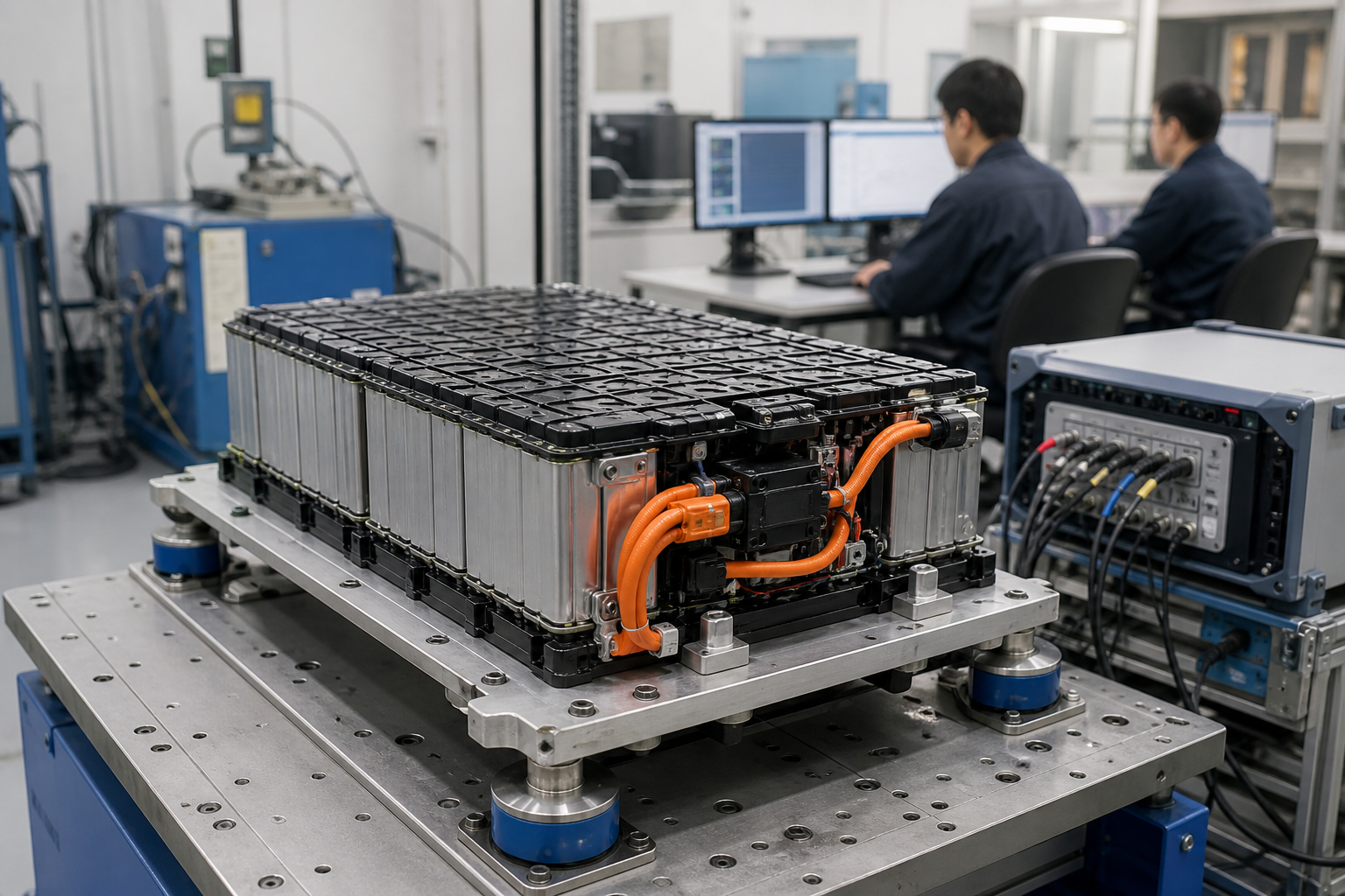
Verification ladder & message fragments
Seven stages with case counts / pass rates · plus message log · not a CTA Demo data · not CTA
- ICD verify 42 · 100%
- Simulation 128 · 98%
- Unit 64 · 97%
- Integration 36 · 94%
- HIL 24 · 92%
- FAT 18 · 100%
- Field — · Planned
Message log fragment
| Time | ID | Signal | Value | Q |
|---|---|---|---|---|
| 12:01:03.120 | 0x18FF50E5 | MaxChargePower | 320.5 | G |
| 12:01:03.140 | 0x18FF51E5 | PackI_Hall | -180.2 | G |
| 12:01:03.200 | 0x18FF10E5 | FaultWord | 0x0000 | G |
| 12:01:04.010 | — | HB_PCS | OK | G |
| 12:01:04.520 | 0x18FF50E5 | MaxChargePower | 318.0 | S |