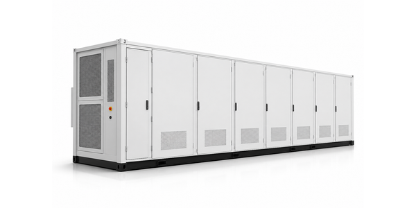
Integrated lithium battery energy storage solutions

CAPACITY & VOLTAGE CUSTOMIZATION

From target power and duration to a verifiable battery system architecture

We derive series/parallel architecture from customer power, energy, duration and operating SOC/temperature windows — then verify the full envelope before configuration freeze.

  • Controlled engineering process

    Load duty definition

    Turn target power, duration and peaks into calculable inputs.

  • Requirement governance

    Voltage-window engineering

    Align cell-to-PCS DC windows and protection boundaries.

  • Assured verification

    Series/parallel architecture

    Build a verifiable topology with energy/power decoupling.

  • Scale delivery

    Interface & derating validation

    Close the loop on PCS interface, derating and dynamic duty.

DEMO DATA · CAP-SIZ-01 · 2026-W32

Sizing snapshot (template)

Project (demo) TC-CV-26-021 · 1.25 MW / 5.0 MWh · 1,331 V
Target power
1.25 MW
Duration
4 h
Usable energy
5.0 MWh
Nominal voltage
1,331 V
DC window
1,050–1,500 V
Temp window
−20–50 °C
Design C-rate
0.40C
Topology
52S-8P × 4 Racks
Program ID
TC-CV-26-021
PCS class
1500 V bi-directional
Design C-rate
0.40C
Freeze rev.
REV-C · PENDING SIGN
Ambient range
−20–50 °C
Altitude limit
< 3,000 m
Aux redundancy
N+1 demo
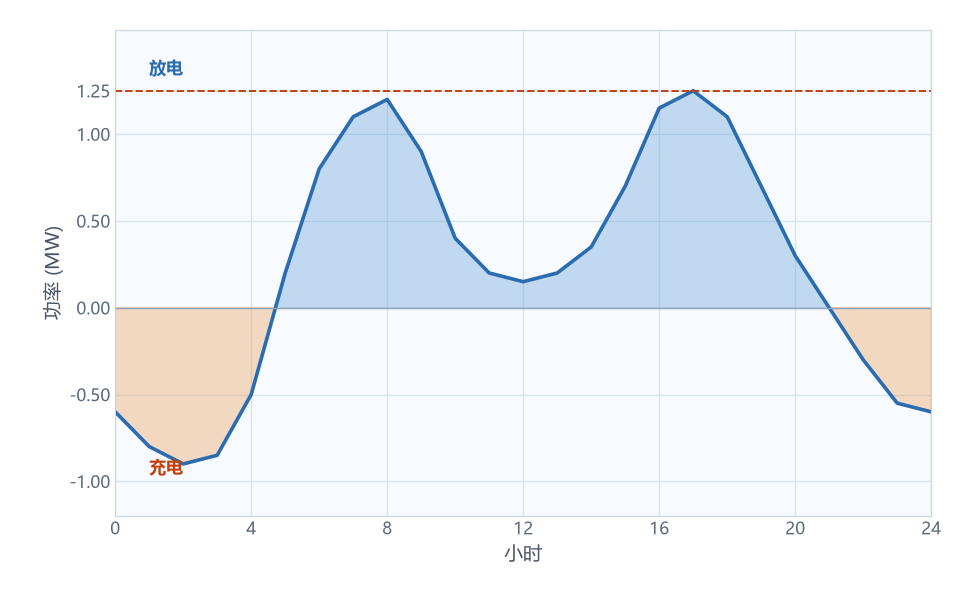
24-hour charge and discharge load strategy
24 h load strategy
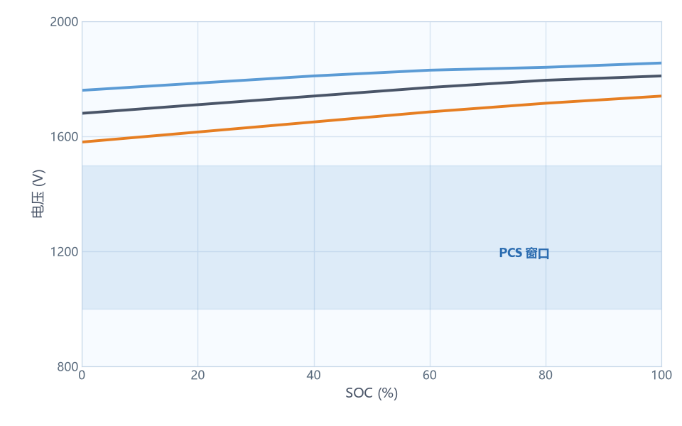
Voltage versus SOC preview across temperatures
Voltage / SOC / temperature

Requirement input and engineering calculation

Customer power, energy, duration and site constraints feed a verifiable calculation chain — not a catalog SKU pick.

Requirement input list (template)

Power

Rated power
1.25 MW
Peak power (10 s)
1.50 MW
Duration @ rated
4.0 h

Energy

Usable energy target
5.0 MWh
Nominal DC voltage
1,331 V
SOC window
10–95%

Environment

Ambient range
−10–45 °C
Altitude limit
< 3,000 m

Interface

PCS DC class
1500 V bi-directional
Auxiliary redundancy
N+1 demo

Engineering calculation (target 5.0 MWh usable)

  1. 01

    Usable target

    E_usable goal

    5.0 MWh

  2. 02

    η×DOD×retention

    0.92 × 0.80 × 0.92

    ÷ 0.677

  3. 03

    Nameplate need

    (5.0+0.035)÷0.677

    ≈ 7.44 MWh

  4. 04

    Architecture check

    4 × 3.343 MWh · margin OK

    13.37 MWh

ItemFormula / noteSample checkRemark
E_nameplate 4 Racks × 3.343 MWh 13.37 MWh —
η_sys DC-side efficiency 92.0% —
DOD window Operating swing 80% —
Degradation (demo) Year-15 allowance 8.0% —
E_aux HVAC + BMS 0.035 MWh —
E_usable Chain result ≈ 9.01 MWh target 5.0 · pass

Architecture built bottom-up — Cell to multi-cabinet BESS (example chain)

Parallel count sets current; series count sets voltage. Each hop adds manufacturing, sampling and safety boundaries.

  1. Cell

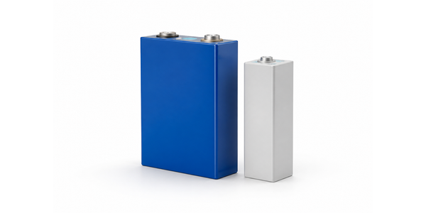
    LFP battery cell

    314Ah LFP

    • Nominal capacity 314 Ah
    • Nominal voltage 3.200 V
    • Voltage range 2.5–3.65 V
  2. Module Battery module

    8S1P

    • Nominal voltage 25.6 V
    • Nominal capacity 314 Ah
    • Energy 8.03 kWh
  3. Pack Battery pack

    52S1P

    • Nominal voltage 166.4 V
    • Nominal capacity 314 Ah
    • Energy 52.20 kWh
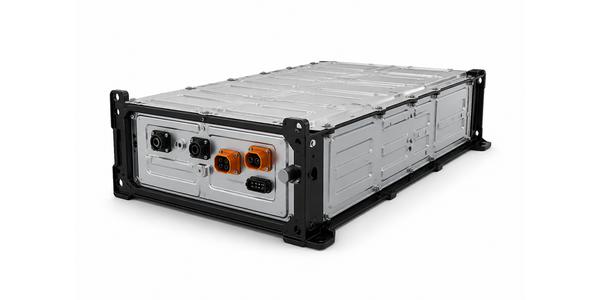
  4. Rack / String

    Battery rack / string

    52 modules series · 8P

    • Nominal voltage 1,331 V
    • Nominal capacity 2,512 Ah
    • Energy 3.343 MWh
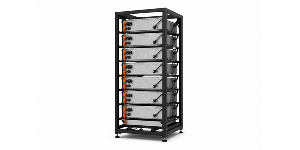
  5. Cabinet

    Battery cabinet

    1 bay / 1 Rack

    • Nominal voltage 1,331 V
    • Nominal capacity 2,512 Ah
    • Energy 3.343 MWh
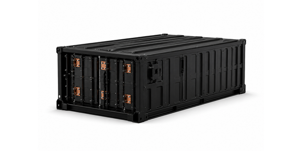
  6. Multi-cabinet BESS

    Multi-cabinet BESS

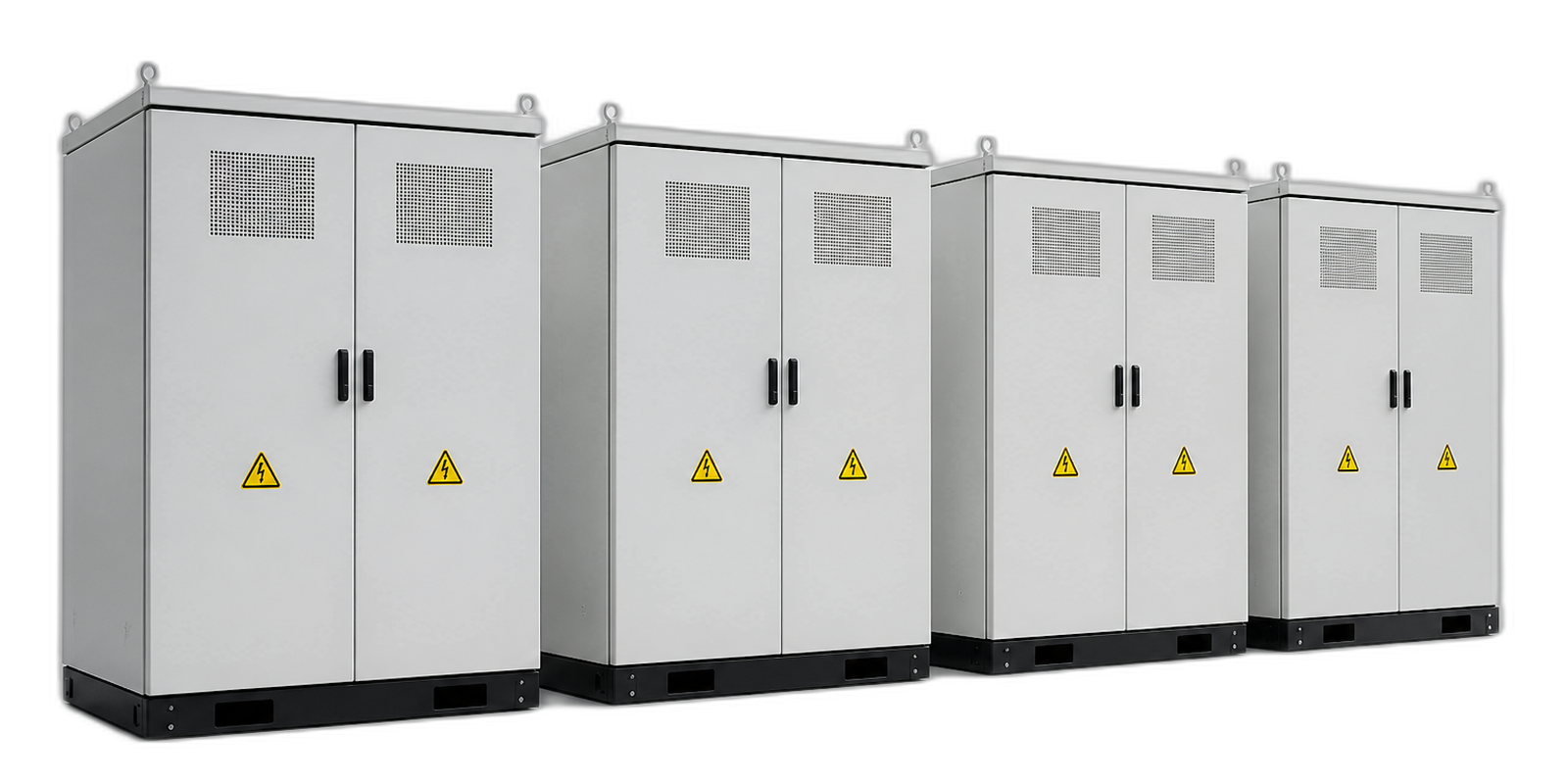
    4 cabinets in parallel

    • Nominal voltage 1,331 V
    • Nominal capacity 2,512 Ah
    • Energy 13.37 MWh

Calc check: 13.37 MWh × 0.92 × 0.80 × (1 − 0.08) − 0.035 MWh ≈ 9.01 MWh (above 5.0 target, margin OK)

The voltage window must fall within executable equipment ranges simultaneously

Cell chemistry, BMS, Pack/Rack, PCS DC/MPPT, protection hardware and grid support must share one overlapping DC window — design locks to that intersection.
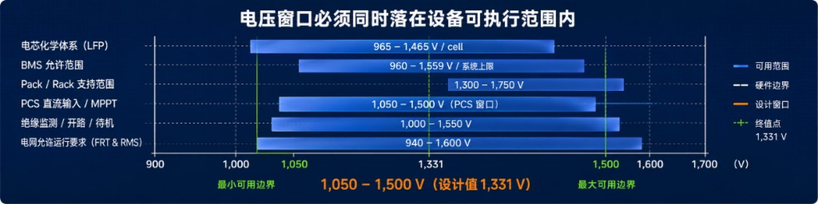
Voltage window overlap across cell, BMS, Pack/Rack, PCS and grid constraints
  • Cell chemistry (LFP) 958–1,485 V (416S stack)
  • BMS allowable 920–1,509 V
  • Pack / Rack allowable 1,000–1,510 V
  • PCS DC / MPPT 1,050–1,500 V
  • Contactor / plug / protection 1,000–1,550 V
  • Grid support (FRT & RMS) 980–1,600 V

SOC × temperature voltage envelope

Architecture is valid only across the full SOC and temperature cube — not at a single nominal point.

SOC × temperature voltage envelope (cell → cluster)

AmbientSOCCell min (V)Cell nom (V)Cell max (V)Rack 416S min (V)Rack 416S max (V)In PCS window?
−20 °C (cold) 10% 2.70 3.20 3.45 1,123 1,435
90% 2.80 3.35 3.65 1,165 1,518 (over max)
25 °C (nominal) 10% 2.85 3.20 3.45 1,186 1,435
90% 2.95 3.35 3.55 1,227 1,477
50 °C (hot) 10% 3.00 3.20 3.45 1,248 1,435
90% 3.10 3.35 3.55 1,290 1,477

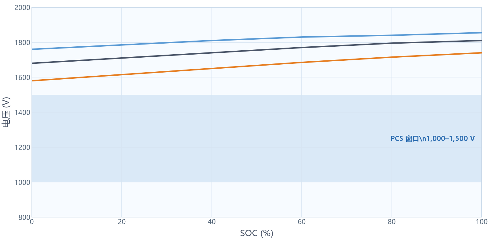
Voltage envelope (Rack 416S)

  • −20°C
  • 25°C
  • 50°C
Rack 416S voltage envelope versus SOC at −20 °C, 25 °C and 50 °C, with PCS window 1,000–1,500 V
  • Voltage

    Cell–Rack 416S · nominal 1,331 V · PCS window 1,050–1,500 V

  • SOC

    Operating 10–95% · protection 5–98% · calibration points defined

  • Temperature

    Charge 0–45 °C · discharge −10–50 °C · derating above 35 °C

Energy and power decoupling

Nameplate energy and instantaneous power follow different constraints — C-rate, thermal path, connector rating and PCS limit must close independently.
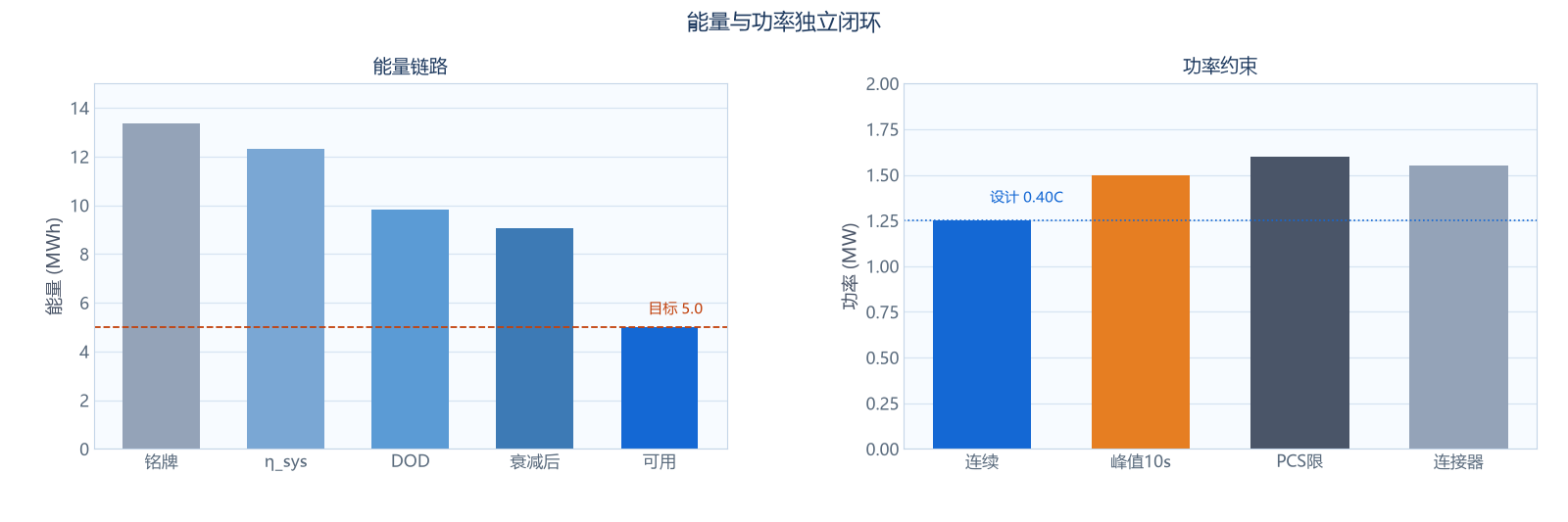
  • Energy sizing from duration, DOD and end-of-life retention — not nameplate alone
  • Power sizing from PCS limit, connector I²t and cell SOP map across SOC/temperature
  • Architecture must satisfy both simultaneously at worst-case operating point
E_usable
5.0 MWh
P_continuous
1.25 MW
P_peak (10 s)
1.50 MW
Design C-rate (demo)
0.40C
Energy chain and power constraint decoupling chart

Voltage / parallel architecture options (template)

Power and current formulas close against PCS and connector limits before option sign-off.

Power is set by current and PCS; energy is set by parallel count and cabinet quantity.

Power limit (MW)

P = V_dc × I_dc × η_pcs

Nominal voltage V_dc
1,331 V
PCS channel I_dc,max
1,350 A
Channel rated power P_rat
≈ 1.80 MW
Continuous power P_cont
1.25 MW
Peak power (10 s)
1.50 MW
Current (continuous)
≈ 1,000 A
Current (peak)
≈ 1,200 A

Energy limit (MWh)

E = N_rack × E_rack

Per-Rack energy E_rack
3.343 MWh
Parallel racks N_rack
4
System nominal E_sys
13.37 MWh
Usable energy (loss/fade)
≈ 9.01 MWh (target 5.0)
Duration E_usable/P_cont
4.0 h
Extend to 5 cabinets (opt.)
≈ 6.25 MWh usable

C-rate (per Rack) 1,000/2,512 = 0.40C — changing series count does not change energy.

OptionSPAhRack VRack MWhηTrade-offStatus
Base 52 8 2,512 1,331 V 3.343 92.0% PCS fit · balanced C-rate Selected
Option 2 52 7 2,198 1,331 V 2.925 91.5% Lower current · more racks Review
Option 3 44 16 5,024 1,126 V 5.657 90.8% Low V · PCS mismatch Rejected

Voltage, power and protection boundaries constrain the final architecture

Operating limits shrink under heat, age and fault — architecture must retain usable energy and power with defined redundancy.

  • DC bus / voltage envelope

    DC bus limit

    1,050–1,500 V overlap with PCS

  • Peak current / power

    Peak current

    Connector I²t · ≈ 1,200 A demo

  • PCS handshake / control

    PCS handshake

    Pre-charge SEQ-07 frozen

  • Thermal derating

    Thermal derating

    −12% @ 40 °C demo

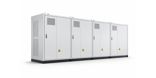
Multi-cabinet BESS under voltage, power and protection boundaries
  • Auxiliary load / safety

    Auxiliary load

    N+1 HVAC · BMS demo

  • Topology / interface

    String bypass

    1 module · ≤ 4% loss

  • Energy retention

    EOL retention

    ≥ 80% @ year 15

  • Protection chain / simulation

    Protection chain

    BMS → PCS ≤ 200 ms

  • Topology / interface

    Prefabricated interface

    1.25 MW expansion / ready to deploy

  • Thermal derating

    Thermal & gas detection

    Lifecycle coverage + multi-sensor fusion

  • PCS handshake / control

    Efficient control

    EMS / BMS / PCS coordinated control

PCS matching — DC window and power handshake

Battery architecture must fit PCS DC limits, pre-charge sequence and power control authority — verified jointly, not assumed.

InterfaceRequirementBattery sidePCS sideResult
DC voltage window Overlap with ≥ 50 V margin 1,050–1,500 V 1,000–1,500 V PASS
Nominal DC voltage Within PCS MPPT band 1,331 V 1,000–1,500 V PASS
Continuous power P_cont ≤ PCS channel 1.25 MW 1.80 MW rated PASS
Peak power (10 s) Within SOP / I²t 1.50 MW 1.80 MW / 10 s PASS
Pre-charge / contactor Sequence frozen SEQ-07 / BMS PCS enable PASS
Power limit map SOP vs PCS derate Demo SOP table PCS curve REVIEW
Fault mapping BMS trip → PCS stop ≤ 200 ms Hard trip input PASS

Dynamic validation and redundancy evidence

Sizing conclusions must survive load, SOC, voltage and current traces before prototype build and DV/PV sampling.

Dynamic duty validation (simulation example)

24 h load curve (demo)
SOC trajectory
Cell temperature rise (hot spot)
Voltage envelope (minimum)

Expansion topology (single cabinet to multi-zone)

Same 1,331 V string architecture — scale capacity and bus zoning from single cabinet to station multi-zone.

  1. Single-cabinet architecture

    Battery cabinet
    • Single Rack
    • Energy 3.343 MWh
    • Power 1.25 MW (peak)
  2. Parallel multi-cabinet (this project)

    Multi-cabinet BESS
    • 4 cabinets in parallel
    • Energy 13.37 MWh (nominal)
    • Power 1.25 MW (PCS-limited)
  3. Segmented bus (mid-term)

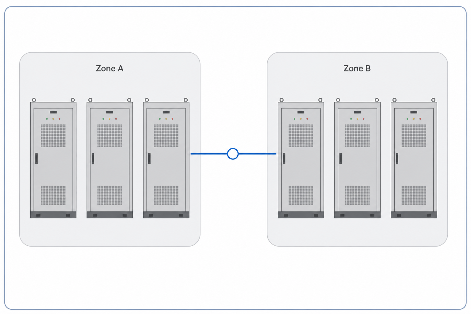
    Dual-zone bus with tie switch schematic
    • Dual-zone bus + tie switch
    • Selective protection & fault isolation
  4. Station multi-zone (long-term)

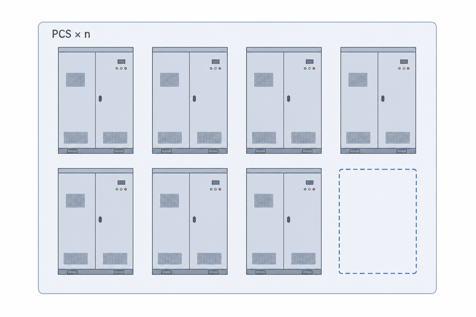
    Station multi-zone PCS parallel expansion schematic
    • Multi-PCS parallel / multi-bus
    • 25% expansion space reserved

Simulation & verification loop (closed iteration)

From requirement modeling to full-system validation — close the capacity and voltage sizing chain.

  1. Requirements & model basis

    Duty, standards and boundary definition

    Done

  2. Electrical model

    PLECS / PSCAD verification

    Done

  3. Thermal simulation

    CFD / FEA verification

    Done

  4. HIL / control validation

    BMS / PCS co-simulation

    Done

  5. Prototype build

    First-article functional check

    Done

  6. Power cycle test

    1,000 cycles +

    In progress

  7. Environmental accessory test

    Temp / vibe / salt fog

    In progress

  8. System test & closeout

    Data loopback and optimization

    In progress

Voltage envelope correlation
Temp-rise correlation (hot spot)
Power-cycle fade curve

Configuration freeze and controlled delivery

Released architecture carries revision ID, BOM baseline, interface ICD and verification evidence — changes follow OEM change control.

  • Architecture calculation report (template)
  • Topology & BOM baseline REV-C
  • Voltage–SOC–temperature envelope sheet
  • PCS compatibility checklist
  • Simulation / HIL evidence pack

Turn target capacity and voltage window into a verifiable BESS architecture

Share load duty, duration and PCS class — we return a verifiable architecture path, not a catalog pick list.