









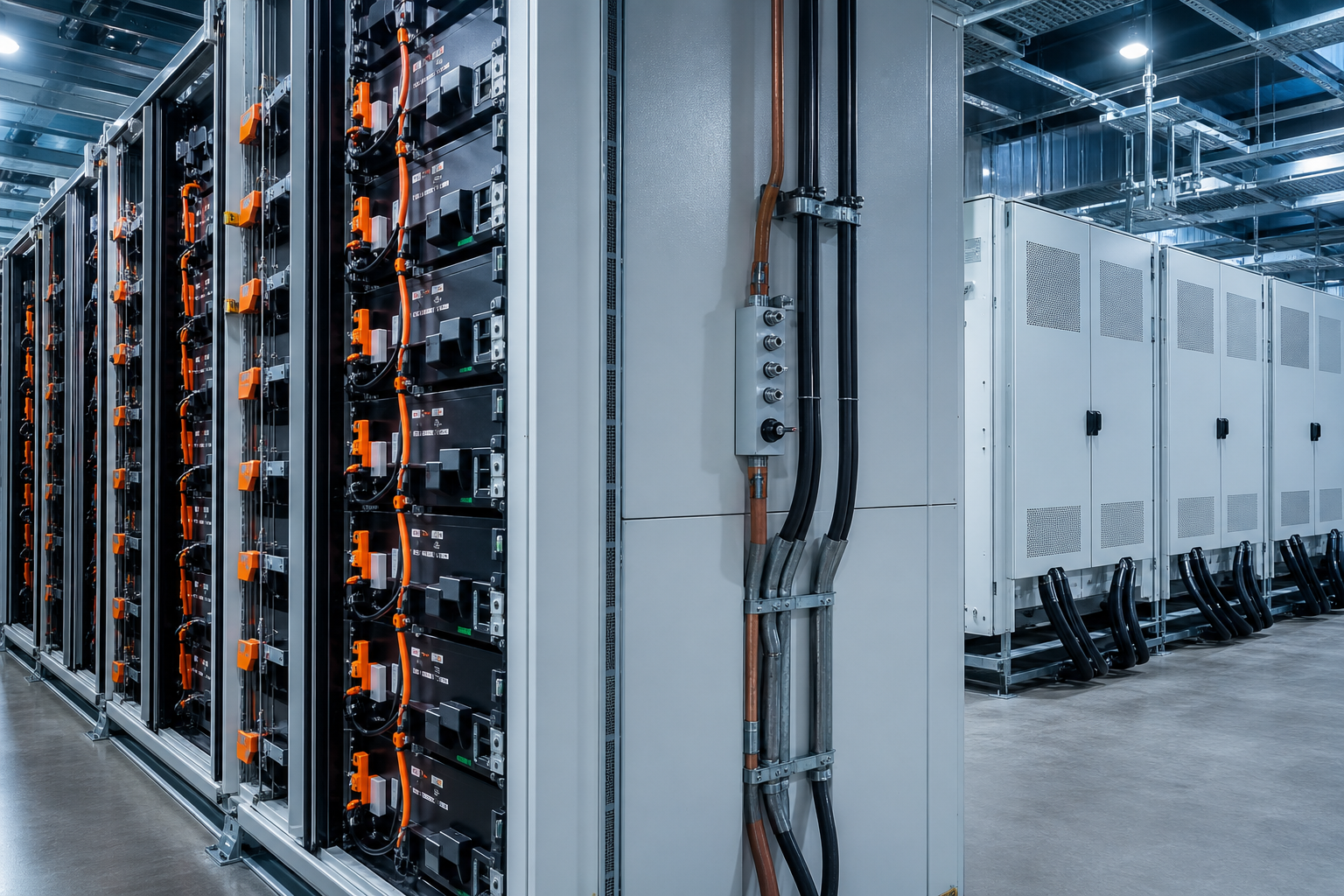
DC electrical interface
Connector class, cable routing, fuse/breaker coordination and HVIL documented in interface drawings.
- DC window
- 1,050–1,500 Vdc
- Rated current
- 2,000 A continuous
- HVIL
- Dual path demo
- Clearance
- Per IEC demo class
PCS / INVERTER INTERFACE
Interface baseline TC-PCS-IF-26-013 DEMO DATA · PCS-IF-01 · 2026-W32
Engineering interface delivery for DC connection, protection, pre-charge, power commands, status feedback, mechanical layout, thermal boundaries and joint verification.

Responsibility matrix
Layer ownership RACI

DC connection & protection
Bus, fuse and contactor

Pre-charge & power commands
Energization handshake

Interlocks & joint FAT
Hardwired safety chain
Battery OEM, PCS supplier and integrator boundaries documented before build · not resolved at commissioning.
| Interface layer | Battery OEM | PCS supplier | Integrator |
|---|---|---|---|
| DC bus & protection | R | C | A |
| Pre-charge sequence | R | R | A |
| Power limit map | R | C | A |
| Status / fault comm | R | R | I |
| Hardwired interlock | R | R | A |
Battery cabinet → interface integration skid → PCS · five paths must handshake before energization. DEMO · schematic only
DEMO · schematic values
Three columns close the energization boundary — connection specs, timing ownership, and command/limit arbitration.
Connector class, cable routing, fuse/breaker coordination and HVIL documented in interface drawings.
Sequence ownership, timing budgets and authority handoff between BMS and PCS controllers.
Who wins when EMS, BMS and PCS limits disagree — priority stack before enable.
DEMO · priority stack
Seven-step closed loop from trigger to ownership — hardwired and supervised paths agree before reset. DEMO DATA · PCS-IF-01 · 2026-W32
DEMO · sample values
Four interface cards at the battery–PCS boundary — tables and demo curve, not a photo collage.
| Channel | BESS | PCS |
|---|---|---|
| CAN-FD | 500 k · BMS | Gateway / adapter |
| Modbus TCP | Optional EMS | Primary PCS port |
| Ethernet | O&M jump | Service NIC |
| Dry contact | Fire / door | E-stop chain |
Demo SVG · altitude × ambient · not a measured chart
DEMO · acceptance sample
Interface Factory Acceptance evidence before site energization — demo tables labeled.
TC-DEMO-PCS-WIR-111 TC-DEMO-PCS-HIL-111 TC-DEMO-PCS-FAT-111 ICD-PCS-2608-111-D | Fault | Source | PCS action | Recovery |
|---|---|---|---|
| CAN loss | BMS / PCS | Safe stop | Auto after link |
| E-stop | Hardwire | Immediate isolate | Local reset |
| Overtemp | PCS / thermal | Derate → trip | Cool-down |
| ΔV exceed | BMS | Block enable | Cell balance |
| Type | Scope | Owner |
|---|---|---|
| Common | DC bus · HVIL · E-stop | OEM + PCS |
| Optional | Modbus map · coolant | Project SI |
| Project-specific | Fire panel · site EMS | EPC |
| Rev | Change | Gate | Status |
|---|---|---|---|
| A | Initial draft | Kickoff | CLOSED |
| B | Pre-charge SEQ-07 | HIL | CLOSED |
| C | Fault map §4 | Joint FAT | CONDITIONAL |
| D | Sign-off pack | Release | REVIEW |
| Item | Criteria | Result | Note |
|---|---|---|---|
| DC continuity | ≤ demo Ω | PASS | Demo |
| Pre-charge time | ≤ 3 s demo | PASS | SEQ-07 |
| Interlock chain | ≤ 100 ms | PASS | Hardwire |
| Comm heartbeat | 3× timeout | CONDITIONAL | Site verify |
| Thermal clearance | 800 mm rear | PASS | Layout |
| ICD pack | Rev D signed | REVIEW | Open 3 |