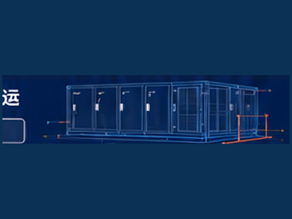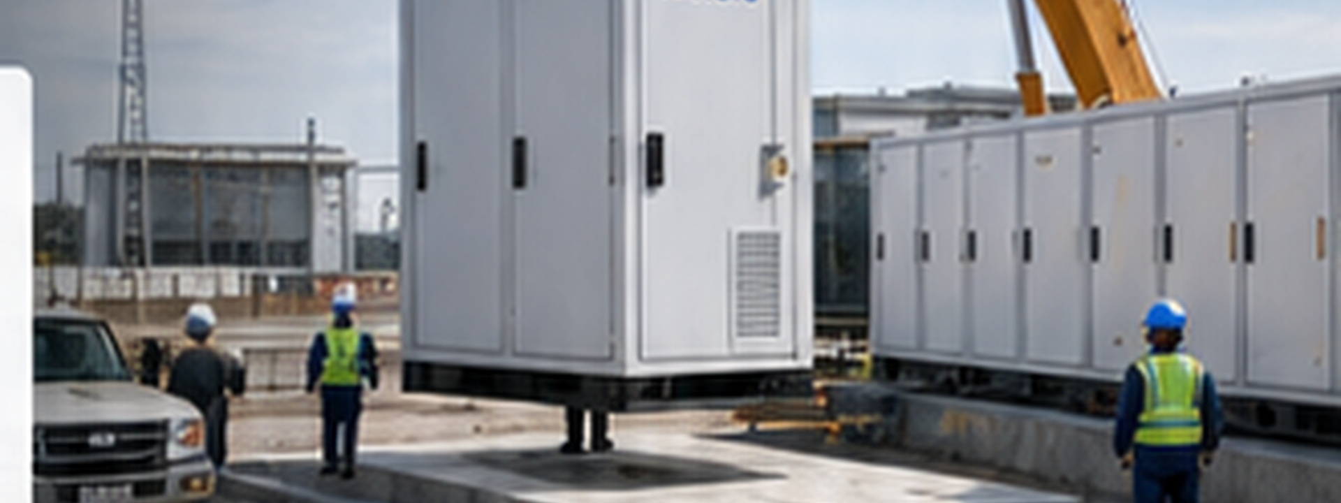
Installation Method|Site interface engineering
From the transport boundary — adapt equipment to the real project site
From site entry to commissioning — interfaces closed, system ready
- Site survey
- Lift & set-down
- Set-down & center
- Anchor fix
- Interface connect
- Commission
-

Site & foundation definition
Survey boundary, elevation, flatness, drainage and earthwork — foundation handover
-

Access & lift planning
Entry route, crane pad, radius, lift points and trial-lift check
-

Cabinet arrangement & service layout
Arrangement, fire gaps, airflow, service aisles and expansion reserve
-

Multi-trade interface closure
Mech / elec / instrument / control / civil matrix — one sheet end to end
Mandatory site-survey inputs
-
 Geology / bearing Foundation conditions
 - Size / space Gate / clear height
-
 Road / turn Radius / grade
 - Lift / pad Lift radius
- Weather / climate Temp / humidity
-
 Water / drain Elevation / grade
 - Cable / pipe Routing / capacity
- Fire / access Depth / distance
- Noise / dust Distance / decay
- Future expansion Capacity / space
Four typical installation scenarios vs interfaces
Same cabinet type · different sites · consistent interfaces
-
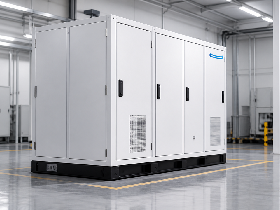
Indoor plant room
-
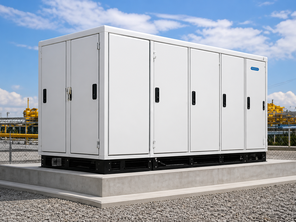
Outdoor foundation
-
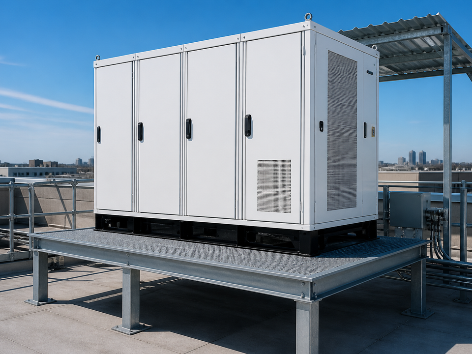
Rooftop platform
-
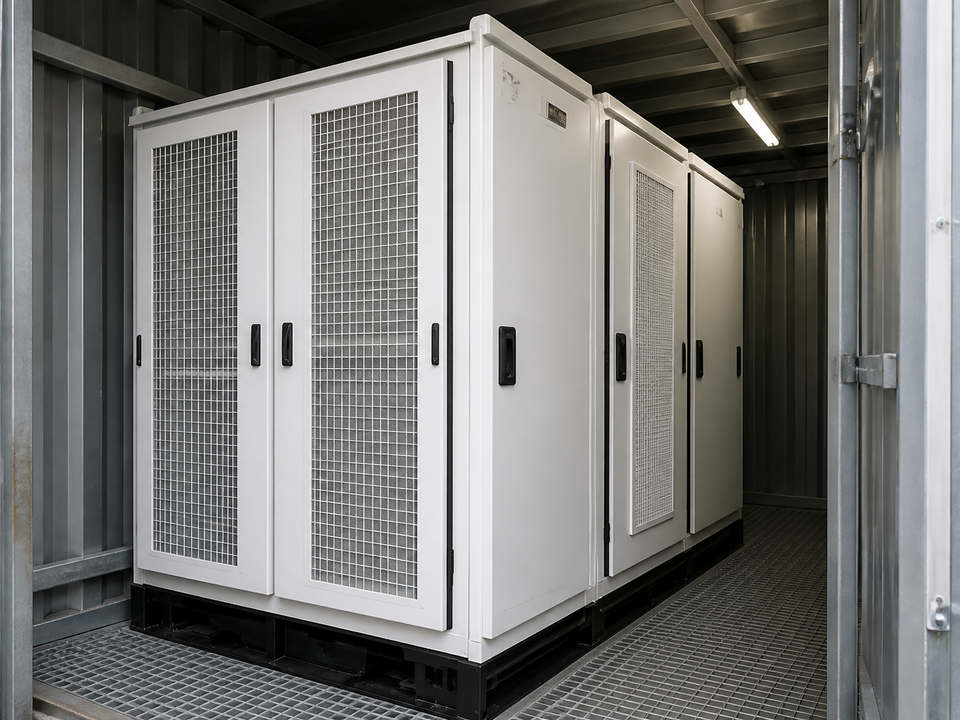
Container / restricted
| Interface | Indoor plant room | Outdoor foundation | Rooftop platform | Container / restricted |
|---|---|---|---|---|
| Load path | Cabinet → pads/base → concrete slab | Cabinet → base → foundation → ground | Cabinet → base → steel platform → beam | Cabinet → base → container floor → ground |
| Foundation / base | Concrete slab / pads | RC pad (≥ 300 mm high) | Steel platform + canopy | Container base / integrated skid |
| Flatness / level | ≤ 3 mm / 2 m | ≤ 3 mm / 2 m | Anti-slip + checker plate | ≤ 3 mm / 2 m |
| Anchoring / fixing | Chemical anchors M14×8 | — | Load to structural beam | Base weld + bolts |
| Earthing | Flat-bar earthing grid | Ring grid / electrode | — | — |
| Drainage / elevation | — | Slope ≥ 1%; flood ≥ 150 mm | Drain / overflow | — |
| Ventilation | HVAC / exhaust duct | — | Top exhaust / natural air | Fans + louvers |
| Clearance / load / IP | Service clear 1.2 / 1.0 / 1.0 m | — | Floor ≤ 7.5 kN/m²; ≤ L/300 | IP54; restricted / temporary |
Foundation conditions must be frozen before equipment arrival
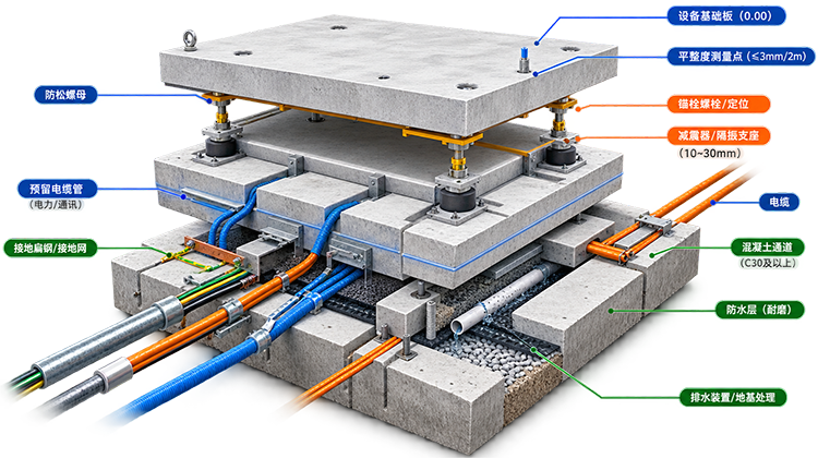
Foundation & embedded-interface responsibility matrix
| Interface | Owner / GC | Civil | M&E install | OEM (equipment) | Hold |
|---|---|---|---|---|---|
| Size / elevation | — | R | — | R | H |
| Flatness / level | — | R | R | R | H |
| Anchor embed / formwork | R | — | R | R | H |
| Embedded pipe / sleeve | R | — | R | R | H |
| Earthing / bonding | — | — | R | R | H |
| Waterproof / drainage | R | — | — | R | H |
| Drain slope / elevation | R | — | — | R | H |
| Opening size / location | R | — | — | R | H |
| Test / witness | — | R | — | R | H |
- R Responsible
- C Cooperate
- H Hold / witness
- — N/A
All H points must be completed and signed off before equipment enters the site.
Access & transport boundary
From factory to install zone — keep installation feasible
-
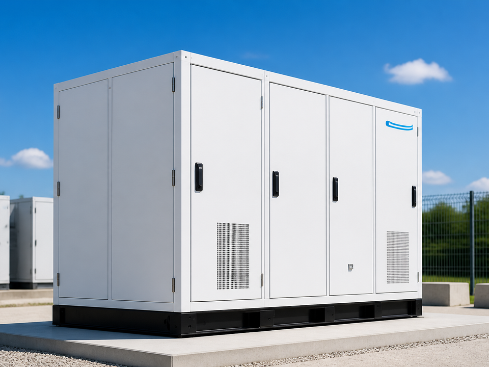
Factory shipping size
W 2.35 m · H 2.90 m · L 6.10 m · 3.85 t per cabinet
-
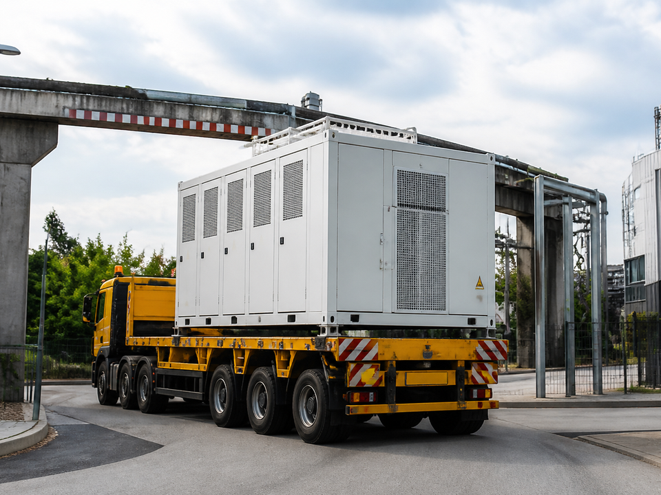
Road height / limits
Height/width · turn radius · bridge clear · overhead lines & visibility
-
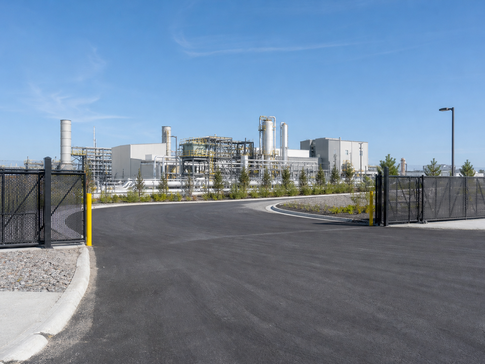
Gate width & turns
Gate clear ≥ 4.0 m · turn radius ≥ 12.0 m · ground load ≥ 60 t
-
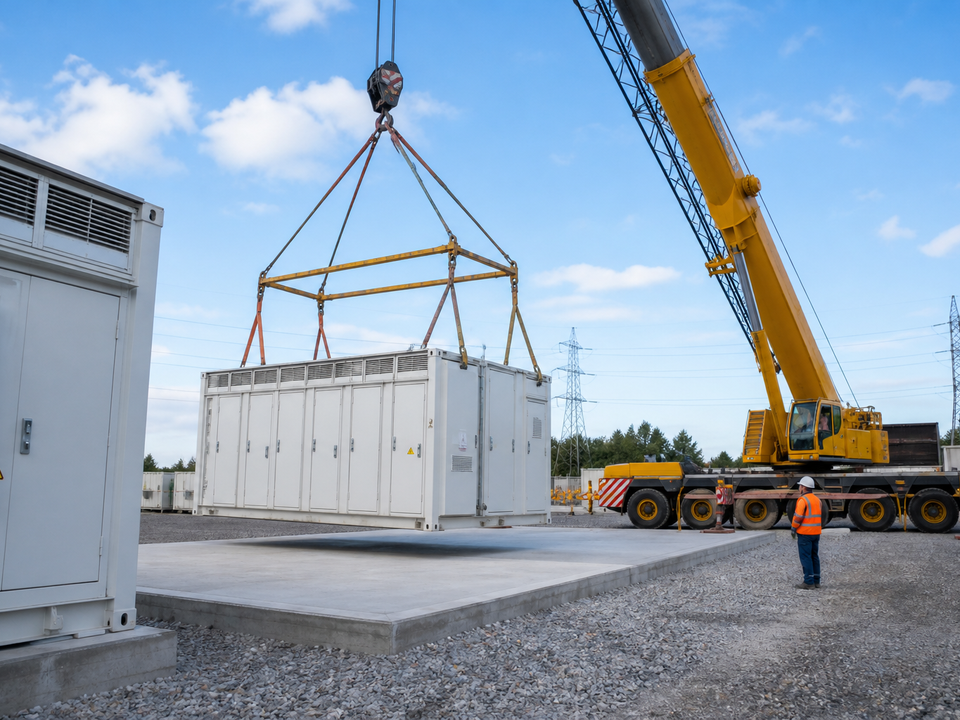
Laydown / unload zone
Bearing ≥ 80 t/m² · flatness ≤ 10 mm · hardstand / drainage
-
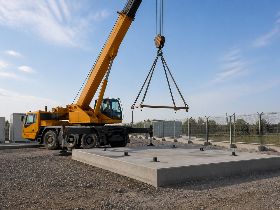
Lift foundation
Bearing ≥ 80 t/m² · radius 18 m · clear forward zone
-
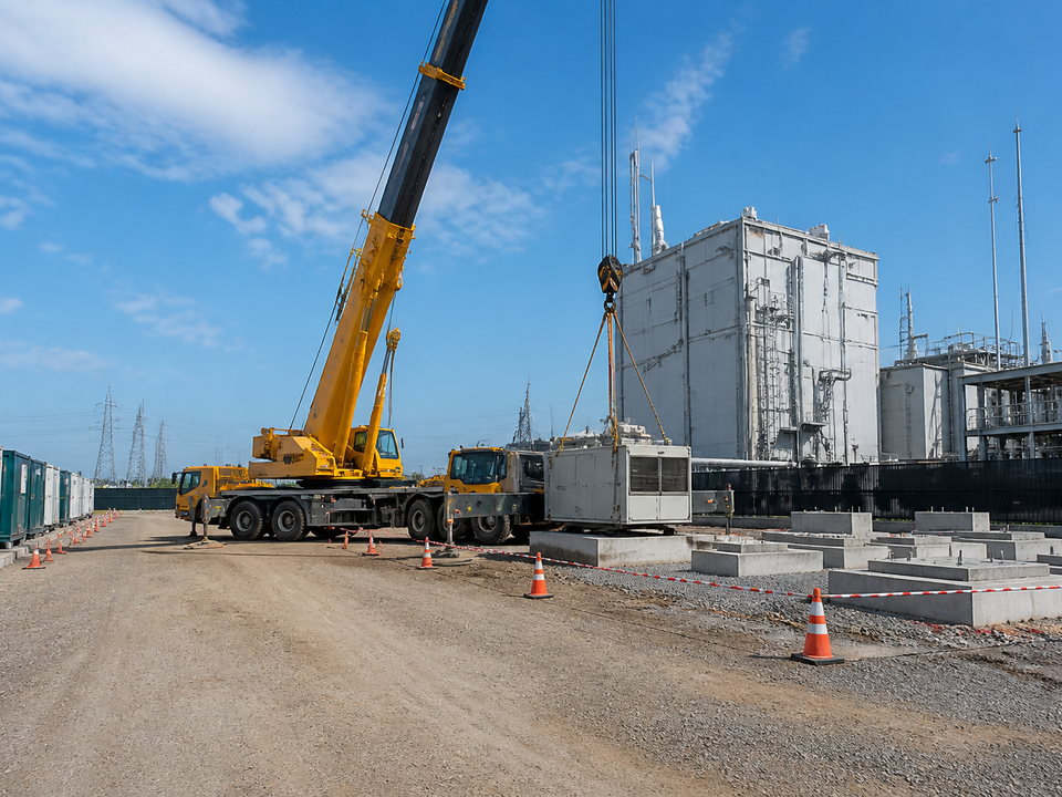
Lift operation zone
Exclusion line · three-way clear · wind assessment
Lifting engineering design (safe, controllable, verifiable)
Freeze lift points, sling angle, CG and crane capacity in the method statement before the first lift.
- Lift method
- 4-point lift 60°
- CG height
- 1,120 mm
- Equipment mass
- 3,850 kg (single cabinet)
- Safety factor
- ≥ 2.0 (lifting gear)
- Max wind
- ≤ 10 m/s (lift)
- Trial lift
- 200 mm trial before main lift
- L 6,100 mm
- W 2,900 mm
- H 2,900 mm
- CG 1,120 mm
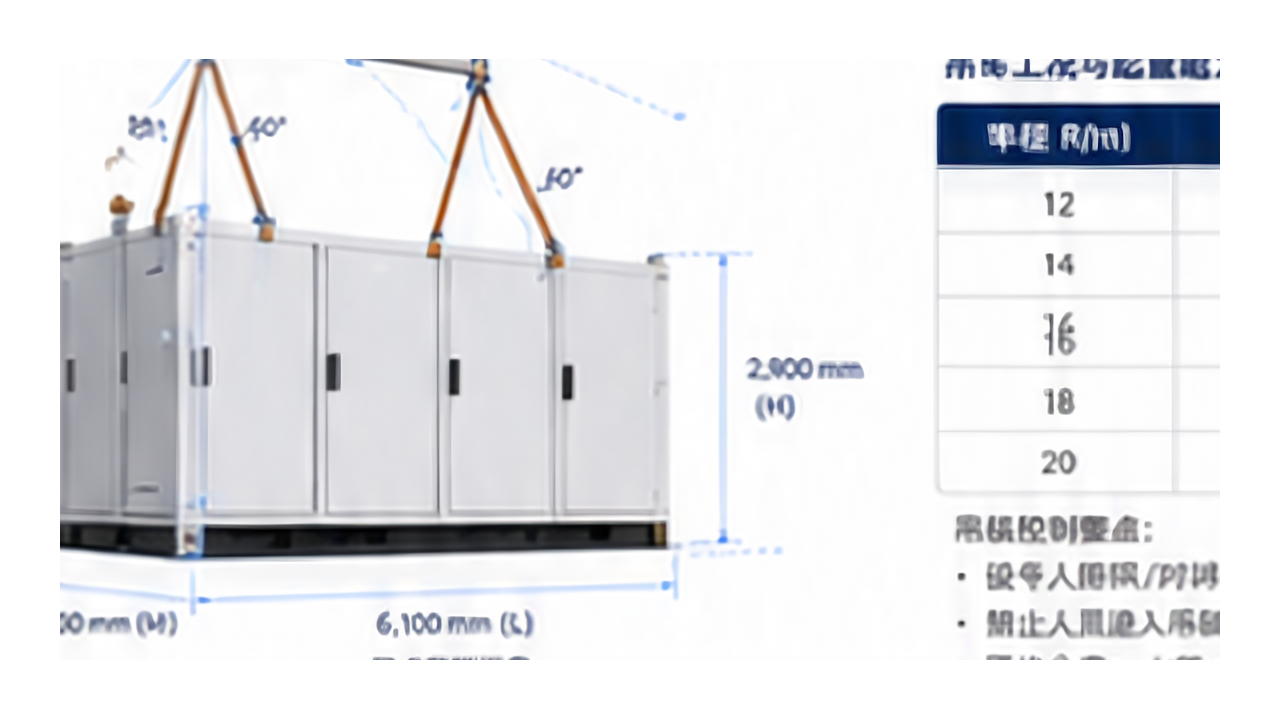
Four-point lift · 60° · L/W/H/CG diagram
| Radius R (m) | Rated (t) | Working load incl. gear (t) | OK? |
|---|---|---|---|
| 12 | 40 | 8.5 | ✓ |
| 14 | 33 | 8.5 | ✓ |
| 16 | 28 | 8.5 | ✓ |
| 18 | 24 | 8.5 | ✓ |
| 20 | 20 | 8.5 | ✓ |
Lift control points
- Banksman + radio; tag-line to control swing
- No personnel under load; stop immediately if wind exceeds limit
- Set-down tolerance: level ≤ 5 mm · elevation ≤ 3 mm
Equipment set-down is a controlled engineering process
-
Pre-work briefing
- Briefing / risk ID
- Method confirmation
-

Gear inspection
- Slings / eyes / shackles
- Certificates complete
-
Trial lift
- 200 mm off ground
- No abnormality
-
Lift into position
- Smooth lift
- Slow travel
-
Orientation adjust
- Align to base lines
- Rotate fine-tune
-
Base centering
- Base / centerline
- Height re-check
-

Leveling
- Shims
- ≤ 1 mm
-
Anchor fix
- Torque control
- Fastening meets spec
-
System re-check
- Procedure confirm
- Site clear confirm
-
Completion acceptance
- Total-station re-survey
- Record archive
Multi-cabinet array and service layout
Performance, fire safety and O and M as one system
Layout types
-
Side-by-side
Back-to-back rows · outer service aisles
-
Face-to-face
Shared center aisle · dual door swing
-
Double-row nested
Compact nesting · side service
-
L-shaped
Corner sites · perimeter service
Key clearances and requirements
| Item | Recommended |
|---|---|
| Front clear width | ≥ 1,200 mm |
| Maintenance aisle | ≥ 1,000 mm |
| Fire aisle | ≥ 1,000 mm |
| O and M spacing (adjacent) | ≥ 1,000 mm |
| Pressure-relief direction | Front / top (see notes) |
| Inlet / exhaust | Forced ventilation |
| Fire zone | Zone capacity under 2,000 kWh |
Airflow and exhaust
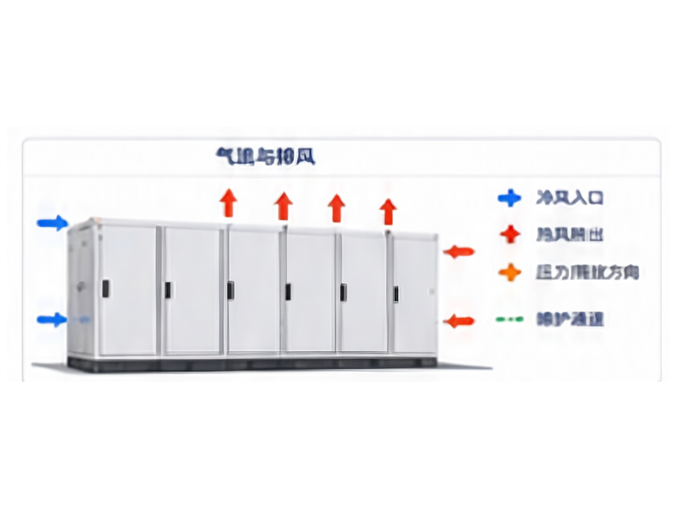
- Cold air inlet
- Hot air exhaust
- Pressure-relief direction
- Maintenance aisle
Interface matrix (mech / elec / control / fire / civil)
Listed interfaces · closed-loop acceptance
| Trade | Interface | Param / load | Owner | Type | Acceptance / notes |
|---|---|---|---|---|---|
| Mech | Anchor / base | M24×8 · 350–400 N·m | Installer | Mech | Torque witness |
| Mech | Cooling ports | DN25 · under 1.0 MPa | Mech | Mech | Pressure / leak |
| Mech | Fill / vent | Per cooling pack | Mech | Mech | Clear / sealed |
| Elec | DC cable entry | DC 1500 V | Elec | Elec | Polarity / insulation |
| Elec | AC cable entry | AC 400 V | Elec | Elec | Insulation test |
| Elec | Earthing / tray | ≤ 4 Ω | Elec | Elec | Earth resistance |
| Control | Comm / interlock | Dual ring | IT / OEM | Control | Point-to-point |
| Control | Temp / flow sensors | Per I/O list | OEM | Control | Range check |
| Fire | Detection | 24 VDC | Fire + OEM | Fire | Signal loop |
| Fire | Suppression | Gas / water-mist | Fire | Fire | Interlock test |
| Civil | Waterproof / insulation | Per site code | Civil | Civil | As-built check |
| Civil | Vent / louvers | Clear exhaust path | Civil | Civil | Path clear |
Environment and site special requirements
Foundation assembly requirements
- Flood elevation
- ≥ 150 mm
- Ground bearing
- Site calc (example 50 / 200 kN/m²)
- Wind design
- ≥ 0.5 kN/m²
- Anti-corrosion coating
- C4 / C5 (salt spray)
- Dust / sand
- Filters · positive pressure
- Pest / fauna
- Seals · protective mesh
Rooftop / indoor control engineering
- Floor load
- ≥ 7.5 kN/m² (example)
- Vibration & noise
- Isolation pads · absorption
- Heat / ventilation
- Inlet/exhaust · pressure relief
- Fire compartment
- Fire rating ≥ 2 h
- Access / service
- Passages and work space
Safety risks and controls
- Lifting risk Lift plan · trial lift / banksman
- Work at height Fall arrest · platforms
- Live interfaces De-energize · prove dead
- Confined space Ventilation · monitoring · attendant
- Weather / storm Lift / stack · lightning watch
- Hot work / welding Tools · fire watch · covers
- Commissioning boundary Load scope · isolation points
Maintenance and replacement access
- Door opening angle ≥ 120°
- Service work aisle ≥ 1,500 mm
- Clearance above fans ≥ 1,200 mm
- Forklift / pallet aisle ≥ 1,800 mm
Validation and acceptance
Verify on interface arrival; hand over when acceptance is complete
-
Foundation / structure
- Flatness ≤ 3 mm / 2 m
- Elevation / datum quick check
- Anchor embed / assembly OK
- Concrete strength meets spec
- Drainage slope clear
-
Mech / elec interfaces
- Cooling pressure / leak
- Water path clear, no seepage
- Cable dress / insulation / torque
- Earth resistance ≤ 4 Ω
- Comm link connectivity
-
System and safety
- Fire interlock / alarm
- Access / CCTV function
- Insulation / hipot tests
- Power-on / self-test
- Thermal / temp-control test
-
Handover pack
- Construction / change drawings
- Interface list / completed items
- Test records / certificates
- Commissioning log / parameters
- Site photos / video playback
- O and M manual
Place equipment smoothly — commission on plan